15
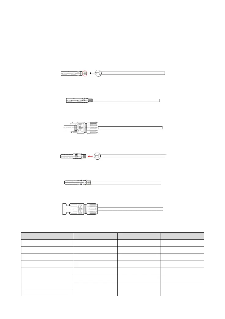
Making the connection wire of the PV module:
Step1: Each MC4 male terminal and female terminal 1pcs(included accessories)
Step2: PV module positive and negative connection wires 2 pcs(red +, black -). The wire length is
determined according to the customer's actual requirement.
Step3: Strip one end of the PV module positive wire for about 5mm, and press the exposed wire to the
inner core of the MC4 male terminal, as shown below:
Step4: Tight press the copper wire and the MC4 male terminal's inner core with a plier and ensure the
connection is secure.
Step5: Unscrew the nut of the MC4 male terminal, insert the inner core into the MC4 terminal, and screw
the nut.
Step6: Strip one end of the PV module negative wire for about 5mm, and press the exposed wire to the
inner core of the MC4 female head, as shown below:
Step7: Tight press the copper wire and the MC4 female head's inner core with a plier and ensure the
connection is secure.
Step8: Unscrew the nut of the MC4 female terminal, insert the inner core into the MC4 terminal, and screw
the nut.
4) Utility input
Recommended wire size of the utility input and the circuit breaker is as below.