Maintenance 5. Arm #1
LS20 Rev.4 89
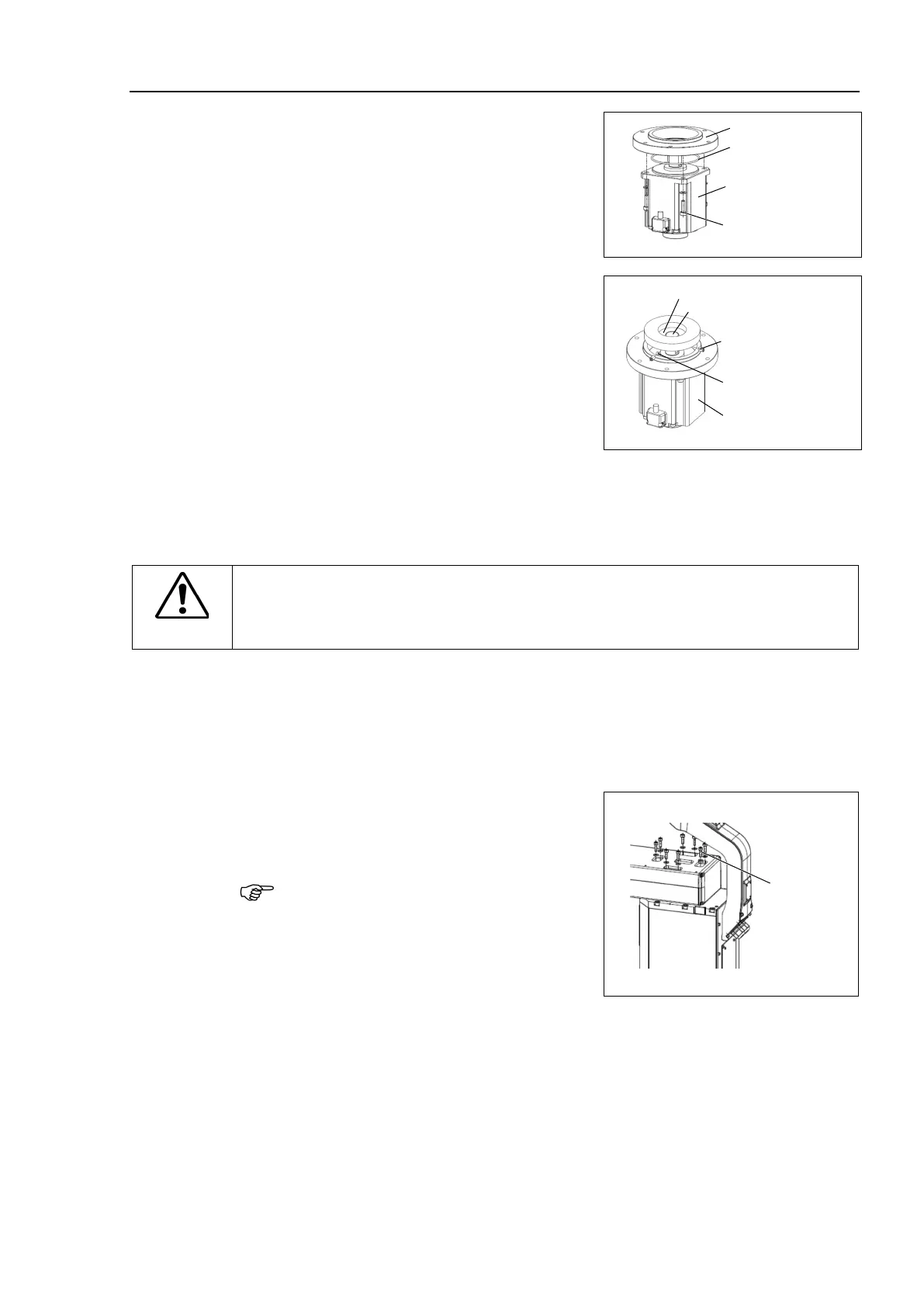
1)
-ring on the motor mounting
surface and mount the motor
flange.
-1A) to the between the
waveform generator and motor.
Grease volume 6g
Mount the waveform generator on the Joint
align the end face of the
generator to the end face of the
shaft.
End face of Waveform Generator
screws vertically on the flat face of the motor shaft. Insert
into the other set screw hole to prevent damage to the motor shaft.
CAUTION
■
See the figure above for the orientation of the waveform generator.
Be sure to
install the waveform generator properly.
Improper installation of the waveform
generator will result in improper function of the Manipulator.
-ring on the motor mounting surface and assemble the top plate. 6-M5×15
To insert the motor, turn it slowly from side to side by hand and push in.
4)
Mount the Joint #1 unit on the Base.
8-M8×25
Secure the Joint #1 motor cables facing toward the back of the Base.
Mount the Arm #1 to the Joint #1 unit.
Tightening torque : 18 N·m
Operating the Manipulator with
improper
tightening torque may cause positioning
gap and damage on the screw and screw
hole.
cover to the Arm #1.
For details, refer to Maintenance: 3.3 Arm #1 cover.
: X10, X110.
Mount the Connector Plate.
For details, refer to Maintenance: 3.4 Connector Plate.
Execute the calibration f
or the Joint #1.
For details refer to Maintenance: 13. Calibration.

 Loading...


