Maintenance 7. Arm #3
110 LS20 Rev.4
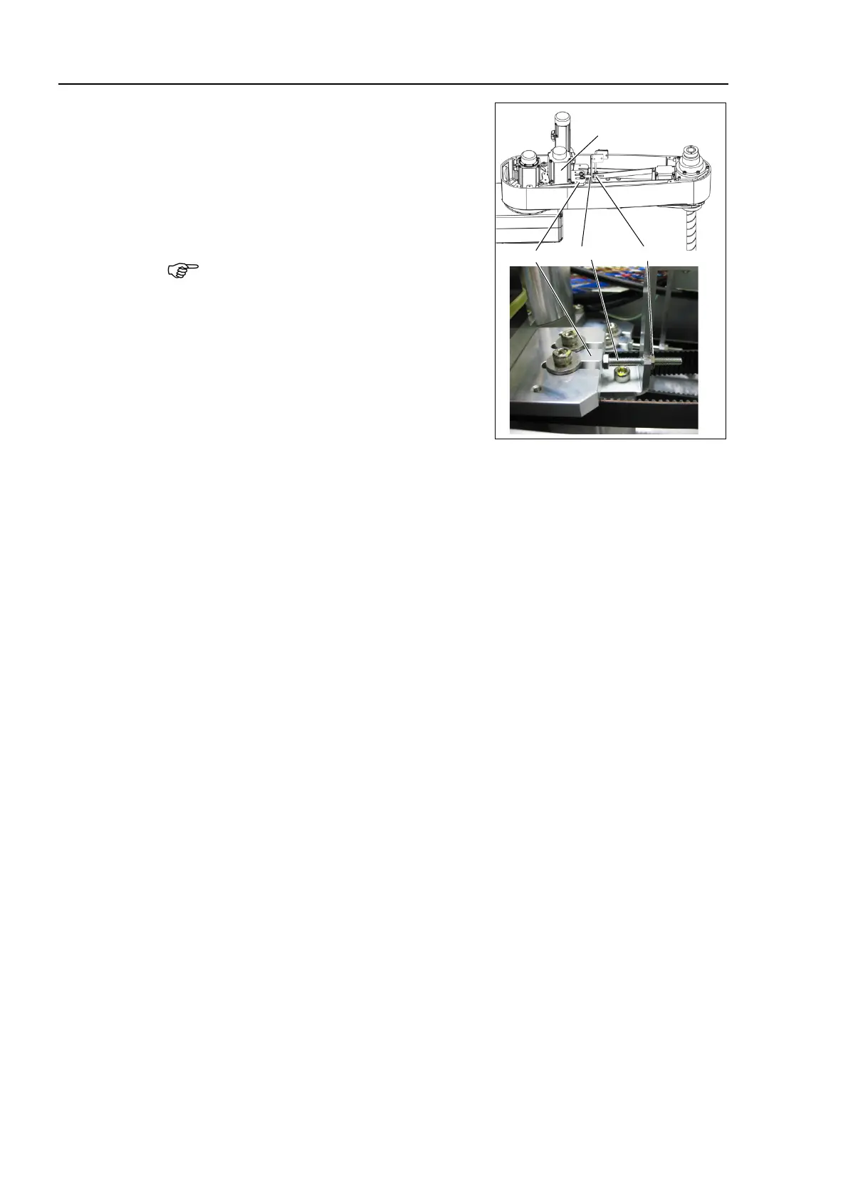
Apply the proper tension to the Z belt, and
then secure the Joint #3 motor unit.
Z belt tension:
93 N (9.5 ± 0.75 kgf)
Axial tension (if being pulled): 186 N
To apply tension to the Joint #3 motor unit,
use the bolt at the front of the plate.
-1
Loosen the nut and turn the bolt.
Push in the Joint #3 motor unit plate
slowly.
-2
After fixing the Joint #3 motor unit,
turn the bolt to leave from the plate.
-3
Check the tension using the ultrasonic tension meter.
Maintenance: 7.4 Checking the Timing Belt Tension.
-4
-1 through (6)-3 until you get appropriate tension.
-5
After the adjustment, put the bolt back to its original position and fix it
with the nut.
7)
X231, X31.
Maintenance: 3.6 User Plate.
9)
Bind the cables with new wire ties at
their original positions as before in
5). Bind the cables with the clip band.
Do not allow unnecessary strain on
the cables.
Arm Top Cover.
Maintenance: 3.1 Arm Top Cover.
Execute the calibration of Joint #3.
For details, refer to Maintenance: 13. Calibration.

 Loading...


