Maintenance 8. Arm #4
LS20 Rev.4 121
Push down the shaft to its lower limit while pressing the brake release switch. Be
sure to keep enough space and prevent
the end effector hitting any
The brake release switch is applied to both Joints #3 and Joint #4.
When the brake release switch is pressed, the respective brakes of the Joint #3 and
Joint #4 are released simultaneously.
shaft falling and rotating while the brake release switch is
because the shaft may be lowered by the weight of an end effector.
Arm Top Cover.
Maintenance: 3.1 Arm Top Cover.
Remove the clip band bundling the
motor cables.
Cut off the wire tie fixing the cable to
the belt tensioner.
At this point, do not cut off the wire tie
fixing the cable to the duct plate.
6)
connectors.
Connectors: X31, X35, X231, X41, X42, X241 (Hold the claw to remove.)
7)
For details, refer to Maintenance: 3.5 User Plate.
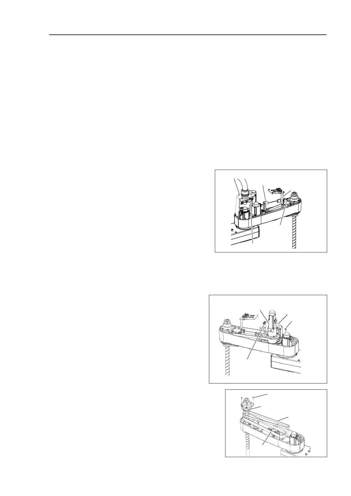
8)
ove the screws for the Joint #3
#4 motor units.
Remove the Joint #3 motor from
the
and pull out the belt.
For details, refer to Maintenance:
7.2 Replacing the Timing Belt.
Pull the Joint #4 motor unit upward.
3-M5×20
+ washer for
slotted hole
3-M5×20
+ washer for
slotted hole
)
Remove the screws mounting the spline
plate.
and pull out the Z

 Loading...


