EPSON Perfection 1670 Photo/Perfection 1270 Revision B
APPENDIX Overview 34
5.1 Overview
This chapter provides supplementary information useful for servicing this product.
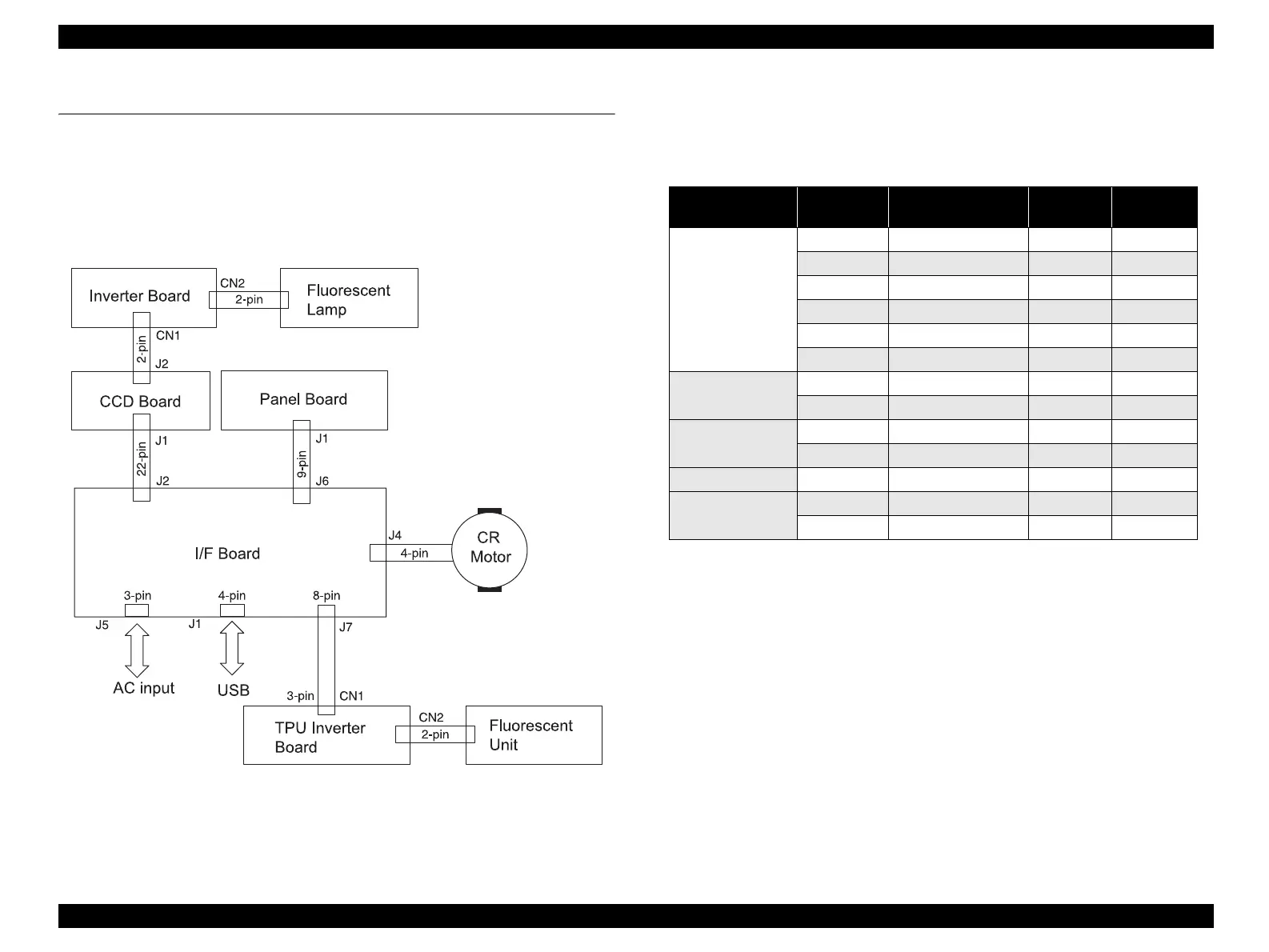
5.1.1 Scanner Connection Diagram
The connection diagram of this product is shown below.
Figure 5-1. Connection Diagram
5.1.2 Connector Connection Table
Table 5-1 indicates the connectors provided for each Board.
Table 5-1. Connector Connection Table
Board Connector Description
Number
of Pins
Reference
Table
I/F Board J1 USB Connector 4 5-2
J2 CCD Board 22 5-3
J4 CR Motor 4 5-4
J5 AC input 3 5-5
J6 Panel Board 9 5-6
J7 TPU Inverter Board 8 5-7
CCD Board J1 I/F Board 22 5-3
J2 Inverter Board 2 5-9
Inverter Board CN1 CCD Board 5 5-8
CN2 Fluorescent Lamp 2 5-9
Panel Board J1 I/F Board 9 5-6
TPU Inverter
Board
CN1 I/F Board 3 5-7
CN2 Fluorescent Unit 2 5-10
 Loading...