EPSON Perfection 1670 Photo/Perfection 1270 Revision B
DISASSEMBLY/ASSEMBLY Disassembly Procedure 23
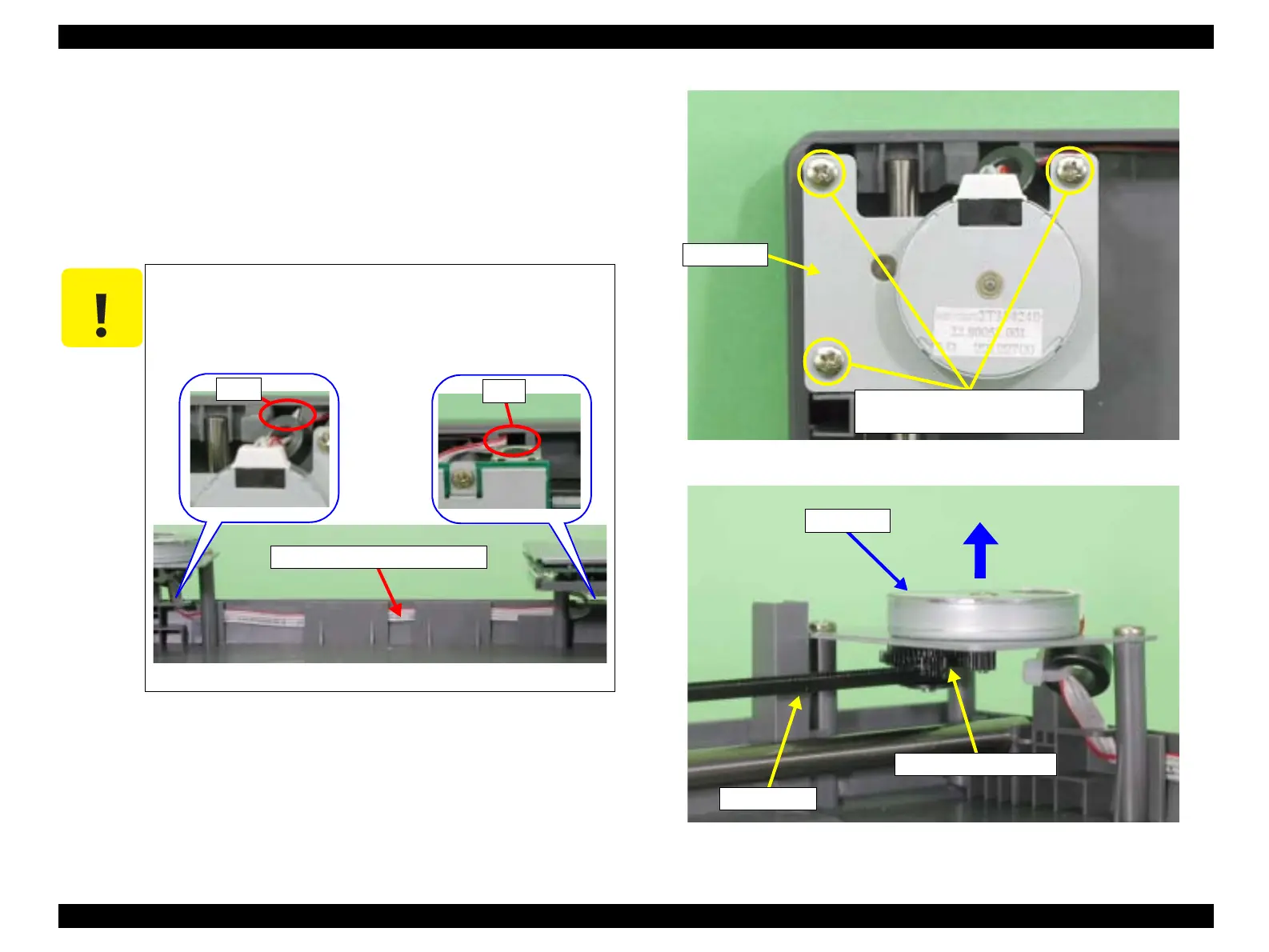
2.2.5 Removal of CR Motor
1. Remove the Upper Housing. (Refer to 2.2.2)
2. Remove the three screws (CBP M3x8) that are securing the CR Motor.
3. Disconnect the CR Motor Connector Cable from the I/F Board. (Refer to Figure 2-9.)
4. After releasing the CR Motor Connector Cable from the groove of the Lower Housing,
pull it out of the holes. (Refer to Figure 2-19.)
5. Lift the CR Motor, remove the Timing Belt from the Transmission Gear, and remove
the CR Motor.
Figure 2-20. Removal of CR Motor Unit
Figure 2-21. Removal of Timing Belt
C A U T I O N
When reinstalling the CR Motor, securely set the Connector Cable
into the holes and groove of the Lower Housing. If the Connector
Cable is set in an isolated state, it may be entangled when the Carriage
operates.
Figure 2-19. Routing of CR Motor Connector Cable
Hole
Hole
CR Motor Connector Cable
CBP (M3x8)
Tightening torque 6-8kgfcm
CR Motor
Timing Belt
Transmission Gear
CR Motor
 Loading...