EPSON Stylus C50/C60/C61/C62 Revision C
Disassembly and Assembly Disassembly 110
4.3.8 Circuit board removal
1. Remove the Upper housing from the printer. (Refer to Section 4.3.1)
2. Remove the ASF unit from the printer. (Refer to Section 4.3.5)
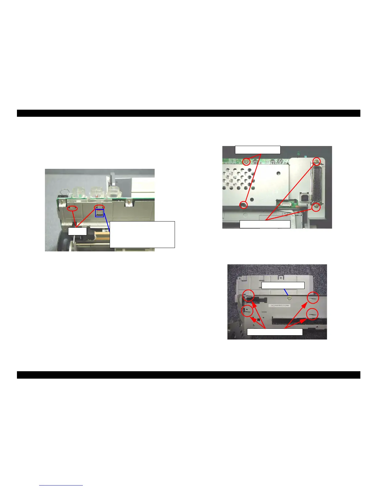
3. Release two hooks for securing the SW button to the M/B mounting plate, and
remove the SW button.
Figure 4-41. SW button removal
4. Disconnect the following six cables from the corresponding connectors on the
Main board.
CR motor connector cable : CN12
PF motor connector cable : CN7
Head FFC : CN8, CN9
HP/PE sensor cable : CN4
Power supply connect cable : CN2
5. Remove four screws (C.B.S. SCREW 3x6 F/Zn, C.B.S. SCREW 3x14 F/Zn) for
securing the Main board shield plate and Main board, and remove them.
Figure 4-42. Circuit board removal
6. Slide the M/B mounting plate to the left side, and release the four hooks of the M/
B mounting plate from the Main board.
Figure 4-43. Hooks on the M/B mounting plate
l
Hooks
The portion enclosing with the blue line
is cut off at the product line of the
Stylus C50 due to a possibility of
HEAD FFC damage caused by HEAD
FFC
contacting with one of the legs of
SW button.
C.B.S. SCREW, 3x6, F/Zn
C.B.S. SCREW, 3x14, F/Zn
Hook on the M/B mounting plate
C.B.S. Screw, 3x6, F/Zn