EPSON Stylus C50/C60/C61/C62 Revision C
Appendix Connector Summary 137
7.1 Connector Summary
7.1.1 Major Component Unit
The Major component units of this printer are as follows.
C418 Main/Main-B/C429 Main/C483 Main-B/C484 Main-B Board
Power Supply Board (C417PSB/PSE, C482 PSH for 42V)
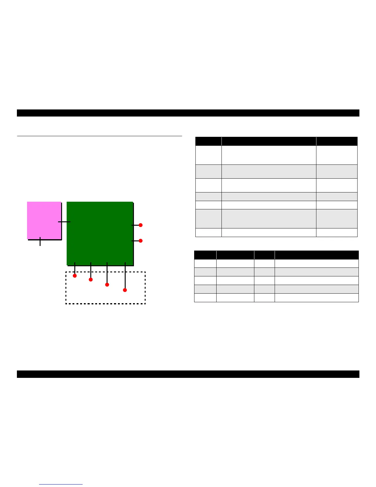
The figure below shows how to connect these components.
Figure 7-1. Connection of the major components
See the following tables for the connector summary for the C418 Main/Main-B board
and each connector’s pin alignment.
CN8, CN9 CN12 CN4
Parallel I/F
CR motor
Printhead
PF motor
C418 MAIN/Main-B/
C429 Main
C483 Main-B
C484 Main-B
CN7
CN1
CN2
HP/PE sensor
C417PSB/PSE,
C482 PSH
CN2
AC power
Printer mechanism
USB I/F
CN3
Table 7-1. Connector summary for C418 Main/Main-B/C429 Main board
Connector Function Table, Refer to
CN1 For connection with the Parallel interface
Refer to 1.3.1
"Parallel Interface
(Forward Channel)"
CN2 For connection with the Power supply board
Table 7-2, Table 7-3
Table 7-4
CN3 For connection with the USB interface
Refer to 1.3.3 "USB
Interface"
CN4 For connection with the HP/PE sensor Table 7-5, Table 7-6
CN7 For connection with the PF motor Table 7-7
CN8, CN9 For connection with the Printhead
Table 7-8, Table 7-9
Table 7-10, Table
7-11
CN12 For connection with the CR motor Table 7-12
Table 7-2. CN2 - Power supply board (Stylus C50)
Pin Signal name I/O Function
1 PSC --- PSC signal
2 GND --- Ground
3 +36V --- Mechanism drive power supply
4 GND --- Ground
5 +5V --- Logic power supply