EPSON Stylus C50/C60/C61/C62 Revision C
Operating Principles Electrical Circuit Operating Principles 46
2.2.2 C418 MAIN/MAIN-B/C429 Main Board
The logic circuit of the C418 Main/Main-B/C429 Main board is composed of the
follows;
Logic line (ASIC, DRAM, P-ROM, EEPROM and so no)
Motor control/drive circuit (CR motor/PF motor)
Head control/drive circuit
Interface control circuit (Parallel I/F, USB I/F)
Sensor circuit
Reset circuit
EEPROM circuit
Switch circuit
LED circuit
The printer mechanism is controlled by the above circuits. Following explains the
major characteristics of this Main board.
Timer IC & Lithium battery are not mounted
Unlike the previous printer (Stylus COLOR 680), the Timer IC and the Lithium
battery are not mounted on these Main boards. So, these printers perform the
Power-on cleaning or Timer cleaning based on the time command which is sent
from the PC through the printer driver. As for the details, refer to 2.1.6.
Use of the 3.3V chips in the logic circuit
The 3.3V regulator (IC8) on the C418 Main/Main-B/C429 Main board generates
3.3VDC by pressuring down the 5VDC to drive several chips for the logic circuit.
Table 2-7. 3.3VDC drive chips & 5VDC drive chips
Unlike the previous printer (Stylus COLOR 680), the panel board is eliminated
and the switches/LED lights are mounted on the Main board.
The transceiver with USB I/F is built in the CPU.
D-RAM
Stylus C50
: 1Mbit D-RAM is mounted on the Main board.
Stylus C60
: 4Mbit D-RAM is mounted on the Main board.
One ASIC controls the all functions on the Main board.
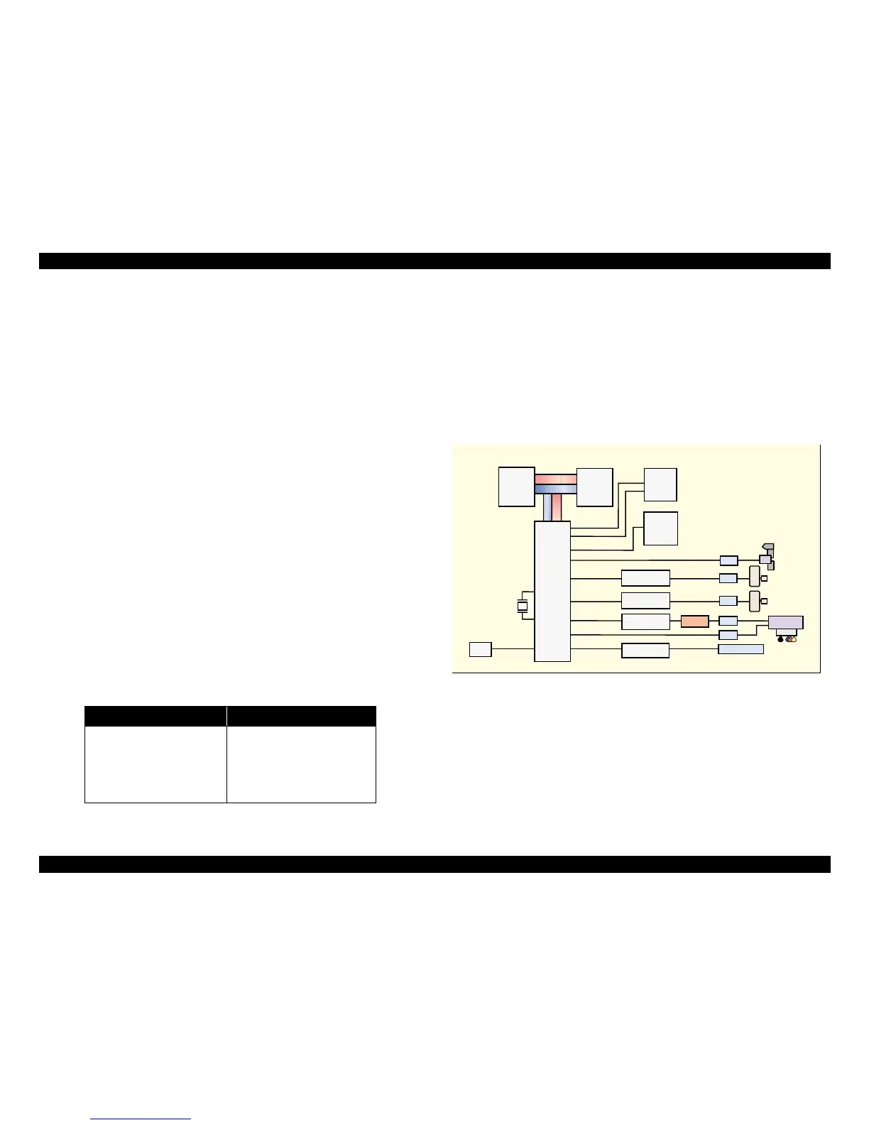
See figure 2-17. for the C418 Main/Main-B board block diagram.
Figure 2-20. Block diagram for the C418 Main/Main-B/C429 Main board
5VDC 3.3VDC
Motor driver (IC10/11)
Reset IC (IC2)
EEPROM (IC3)
Parallel controller (IC7)
ASIC (IC1)
D-RAM (IC5/IC4)
P-ROM (IC6/IC5)
Parallel controller (IC7)
Common driver (IC9/IC19)
P-ROM
(SOJ) 8M
(IC6/IC5)
Address
Data
D-RAM 4M
(IC5/IC4)
E01A21CB
CPU (IC1)
Reset IC
(IC2)
EEPROM
(IC3)
Motor Driver
(IC10)
Motor Driver
(IC11)
Common
Driver (IC9/IC19)
Parallel I/F IC
(IC7)
Q2&Q3
CN3
USB
CN4
CN7
CN12
CN9
CN8
CN1 Parallel I/F
Head
PF Motor
CR Motor
HP/PE Sensor
CR2
* There is difference of IC location between the Stylus C50 and the Stylus C60.
(A/B) : A means the location for the Stylus C50.
B means the location for the Stylus C60.
* There is difference of IC location between the Stylus C50 and the Stylus C60.
(A/B) : A means the location for the Stylus C50.
B means the location for the Stylus C60.