EPSON Stylus C67/C68/D68 Revision A
DISASSEMBLY/ASSEMBLY Disassembly Procedures 57
4) Disconnect the four connectors from the Main Board.
(See 4.3.2.1 Removing Main Board Step 3)
CN5: CR Motor Connector
CN7: CR Encoder FFC
CN8: Head FFC
CN9: PF Sensor Cable
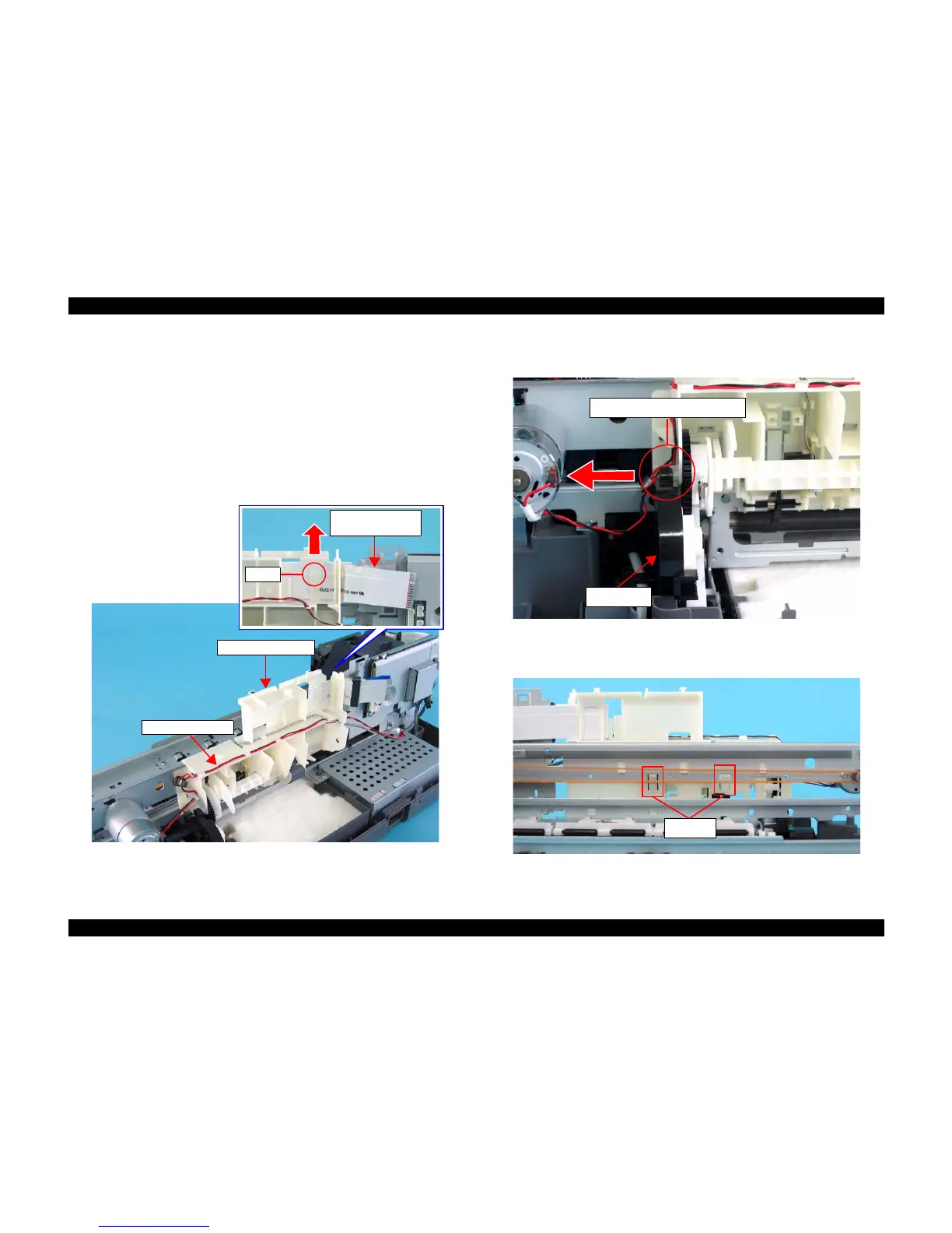
5) Release both the CR Encoder FFC and the Head FFC from the tab of the
Holder Shaft Unit.
6) Disconnect the CR Motor Cable from the Holder Shaft Unit.
Figure 4-33. Removing Holder Shaft Unit (1)
7) Slide the concave portion of the Pump Unit toward the direction of the arrow,
and release the convex portion of the Holder Shaft Unit.
Figure 4-34. Removing Holder Shaft Unit (2)
8) Releasing two tab As that secure the Holder Shaft Unit to the Main Unit,
Remove the Holder Shaft Unit upward.
Figure 4-35. Removing Holder Shaft Unit (3)
CR Encoder FFC/
Head FFC
Tab
Holder Shaft Unit
CR Motor Cable
Concave and Convex Portions
Pump Unit
Tab As

 Loading...


