EPSON Stylus C67/C68/D68 Revision A
DISASSEMBLY/ASSEMBLY Disassembly Procedures 65
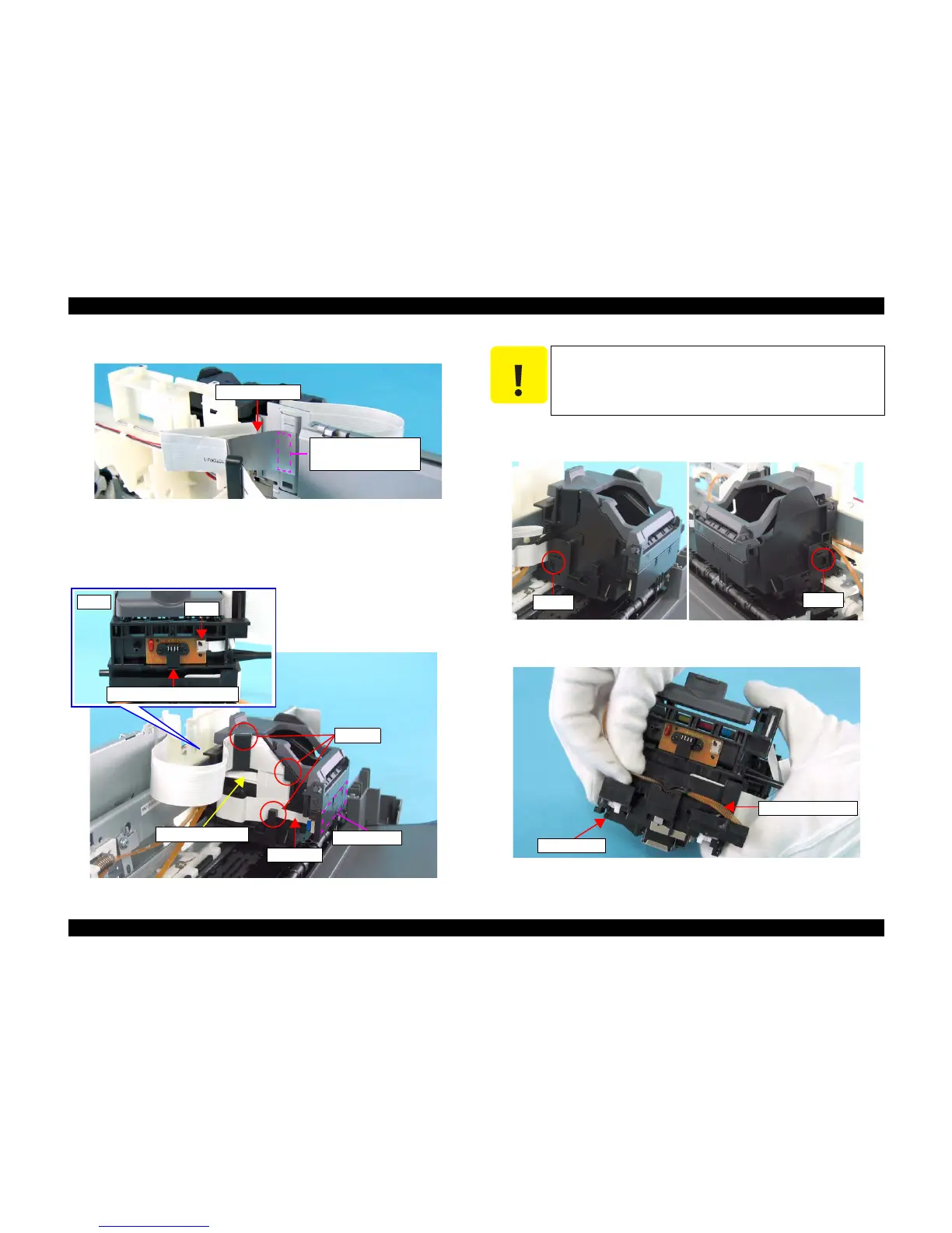
8) Remove the Shield Plate FFC from the Main Unit Frame.
Figure 4-51. Removing Shield Plate FFC
9) Remove the CSICFFC from the CSIC Board.
10) Disconnect the CR Encoder FFC (CN1) from the CR Encoder Sensor Board.
11) Release the three FFCs from the three notches.
Figure 4-52. Removing FFC
12) Release the two tabs of the IC Holder, slide the holder toward you, and
remove both the CR Unit and the CR Timing Belt from the Main Unit.
Figure 4-53. Removing CR Unit (1)
13) Remove the CR Timing Belt from the CR Unit.
Figure 4-54. Removing CR Unit (2)
Shield Plate FFC
Double-sided tape
attaching location
Rear
CN1
CR Encoder Sensor Board
Notches
CSIC Board
CSICFFC
CR Encoder FFC
C A U T I O N
Make sure to support the CR Unit with your hands so as not to drop
it, or the nozzle surface of the printhead may be damaged.
Tab
Tab
CR Timing Belt
CR Unit

 Loading...


