EPSON Stylus C67/C68/D68 Revision A
DISASSEMBLY/ASSEMBLY Disassembly Procedures 64
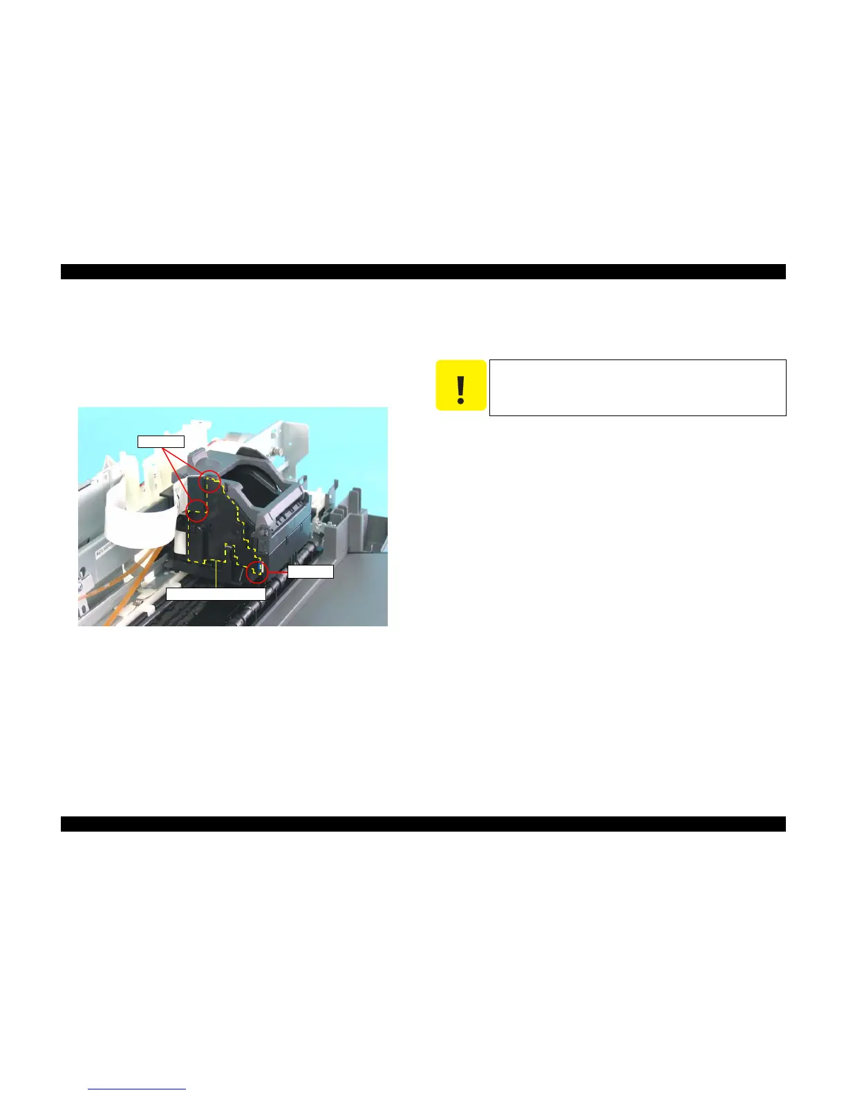
4.3.3.9 CR Cable Head Cover
1) Remove the Housing, Upper. (p43)
2) When removing the CR Cable Head Cover, follow the steps mentioned below.
1. Slide the CR Cable Head Cover downward, and release tab As.
2. Release tab B, slide the CR Cable Head Cover upward, and remove the
CR Cable Head Cover.
Figure 4-50. Removing CR Cable Head Cover
4.3.3.10 CR Unit
1) Remove the Panel Board. (p54)
2) Remove the Front Frame. (p62)
3) Disconnect the two connectors from the Main Board.
(4.3.2.1 Removing Main Board Step 1 through Step 3)
CN7: CR Encoder FFC
CN8: Head FFC
4) Disconnect the CR Encoder FFC and the Head FFC from the Holder Shaft
Unit. (See 4.3.3.2 Removing Holder Shaft Unit Step 5)
5) Disconnect the CR Timing Belt.
(4.3.3.5 Removing CR Timing Belt Step 3 through Step 4)
6) Remove the CR Encoder Scale. (p63)
7) Remove the CR Cable Head Cover. (p64)
Tab B
CR Cable Head Cover
Tab As
C A U T I O N
As the Head FFC and the CR Encoder FFC is attached to each
other with glue, be careful not to remove them separately.

 Loading...


