Epson Stylus C58/C59/ME 2/C79/D78/C90/C91/C92/D92/T20/T20E/T23/T26/S20/T10/T11/ME 30/T21/T24/T27/S21 Revision E
DISASSEMBLY/ASSEMBLY Procedure Specific to Epson Stylus C58/C59/ME 2 66
Confidential
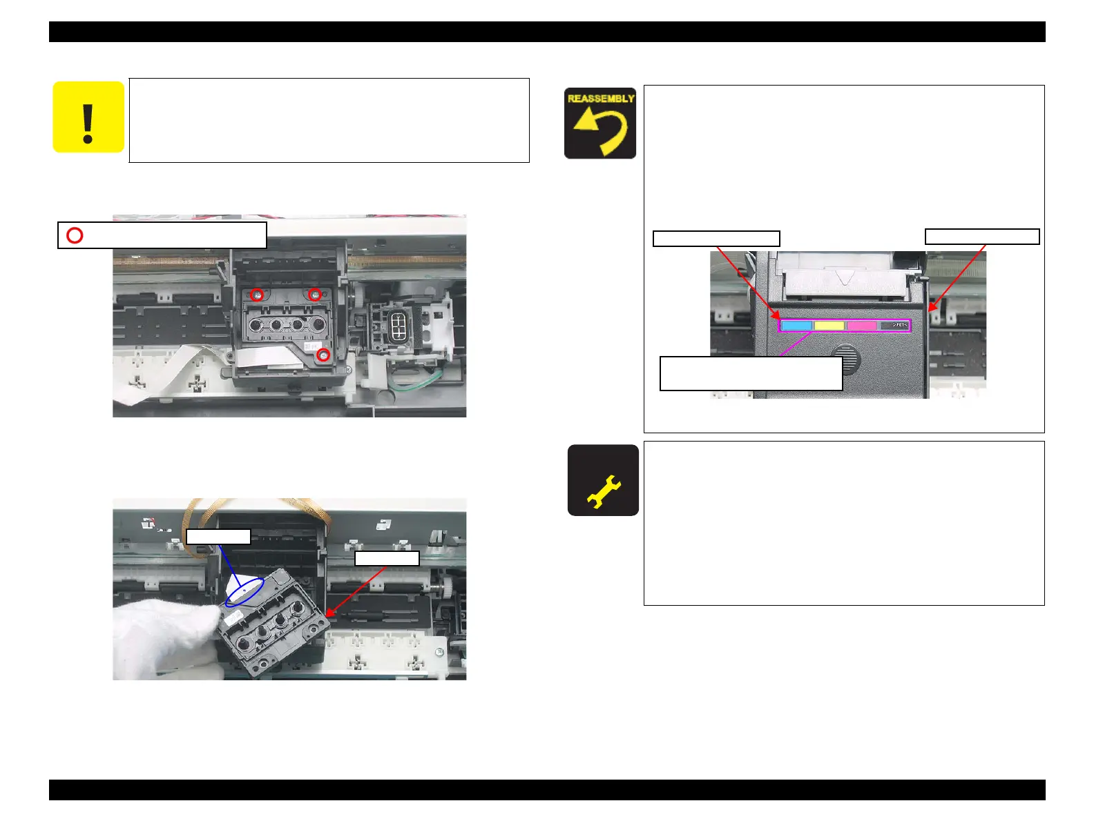
9. Remove the screws (x3) that secure the Printhead, and lift up the Printhead
with a longnose pliers.
Figure 4-87. Removing Printhead (1)
10. Disconnect the Head FFC (x1) from the connector (x1) on the Printhead, and
remove the Printhead.
Figure 4-88. Removing Printhead (2)
Do not touch or damage the nozzles or the ink supply needles of the
Printhead.
C.B.P 2.5X8 (Torque: 3±1Kgf.cm)
When installing the Holder Board Assy, make sure to check if
the assy is properly installed in the right position. The assy is
likely to be installed in the wrong position.
The Ink Position Label is not included in the Cartridge Cover.
When replacing the Cartridge Cover, order the label
separately and attach the Ink Position Label to the place shown
below.
Figure 4-89. Installing Ink Position Label
A D J U S T M E N T
R E Q U I R E D
After removing/replacing the Printhead, perform the adjustment
in the following order. (Refer to Chapter 5
“ADJUSTMENT”)
1. “Ink Charge” (only after replacement)
2. “Head ID Input” (only after replacement)
3. “TOP Margin Adjustment”
4. “First Dot Adjustment”
5. “Head Angular Adjustment”
6. “Bi-D Adjustment”
7. “PF Band Adjustment”
Cartridge Cover
Ink Position Label
Install the label in this position with
Black to the right.