Epson Stylus C58/C59/ME 2/C79/D78/C90/C91/C92/D92/T20/T20E/T23/T26/S20/T10/T11/ME 30/T21/T24/T27/S21 Revision E
DISASSEMBLY/ASSEMBLY Disassembling Printer Mechanism 56
Confidential
4.5.9 Main Frame
Part/Unit that should be removed before removing LD Roller/ASF Unit
Upper Housing /Hopper /Main Board /Print Head /CR Scale /CR Motor /CR Unit /
Timing Belt
Removal procedure
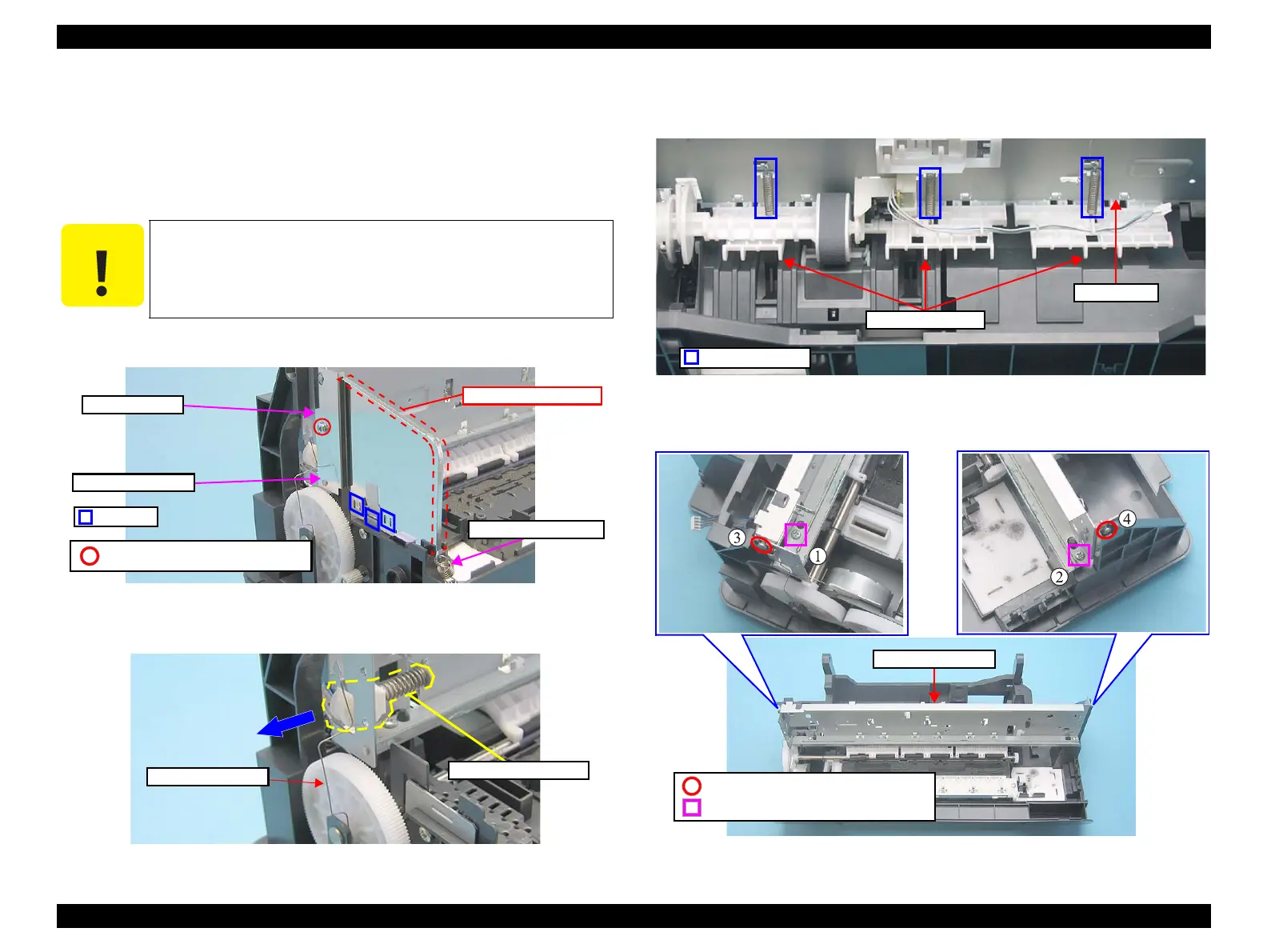
1. Remove the screw and the Grounding Spring SPL, and remove the Shield
Plate L while releasing the hooks and the positioning hole.
Figure 4-53. Removing Shield Plate L
2. Remove the PF Roller Grounding Spring.
3. Remove the Driven Pulley Holder from the notch of the Main Frame.
Figure 4-54. Removing Grounding Spring and Driven Pulley Holder
4. Remove the Extension Springs (x3) from the hooks of the Main Frame and the
guide pins of the Upper Paper Guide.
Figure 4-55. Removing Extension Springs
5. Remove the screws (x4) that secure the Main Frame to the Frame Base.
Figure 4-56. Removing Main Frame (1)
Exercise care to avoid injuring with the sharp edges around the
Shield Plate L shown in the figure below.
Positioning Hole
C.B.S 3X6 (Torque: 6±1Kgf.cm)
Hooks
Shield Plate L
Grounding Spring SPL
Caution! Sharp edges
Main Frame
Extension Springs
Upper Paper Guide
C.P 3X4 (Torque: 4±1Kgf.cm)
C.B.S-(P2) 3X6 (Torque: 8±1Kgf.cm)