Epson Stylus C58/C59/ME 2/C79/D78/C90/C91/C92/D92/T20/T20E/T23/T26/S20/T10/T11/ME 30/T21/T24/T27/S21 Revision E
DISASSEMBLY/ASSEMBLY Disassembly Procedures 37
Confidential
4.2 Disassembly Procedures
This section explains the procedures for disassembling the product.
Unless otherwise stated, reassembly should be carried out in the reverse order of the
disassembly procedure.
For detailed engagement relations among main components, refer to the exploded
diagrams in the Appendix.
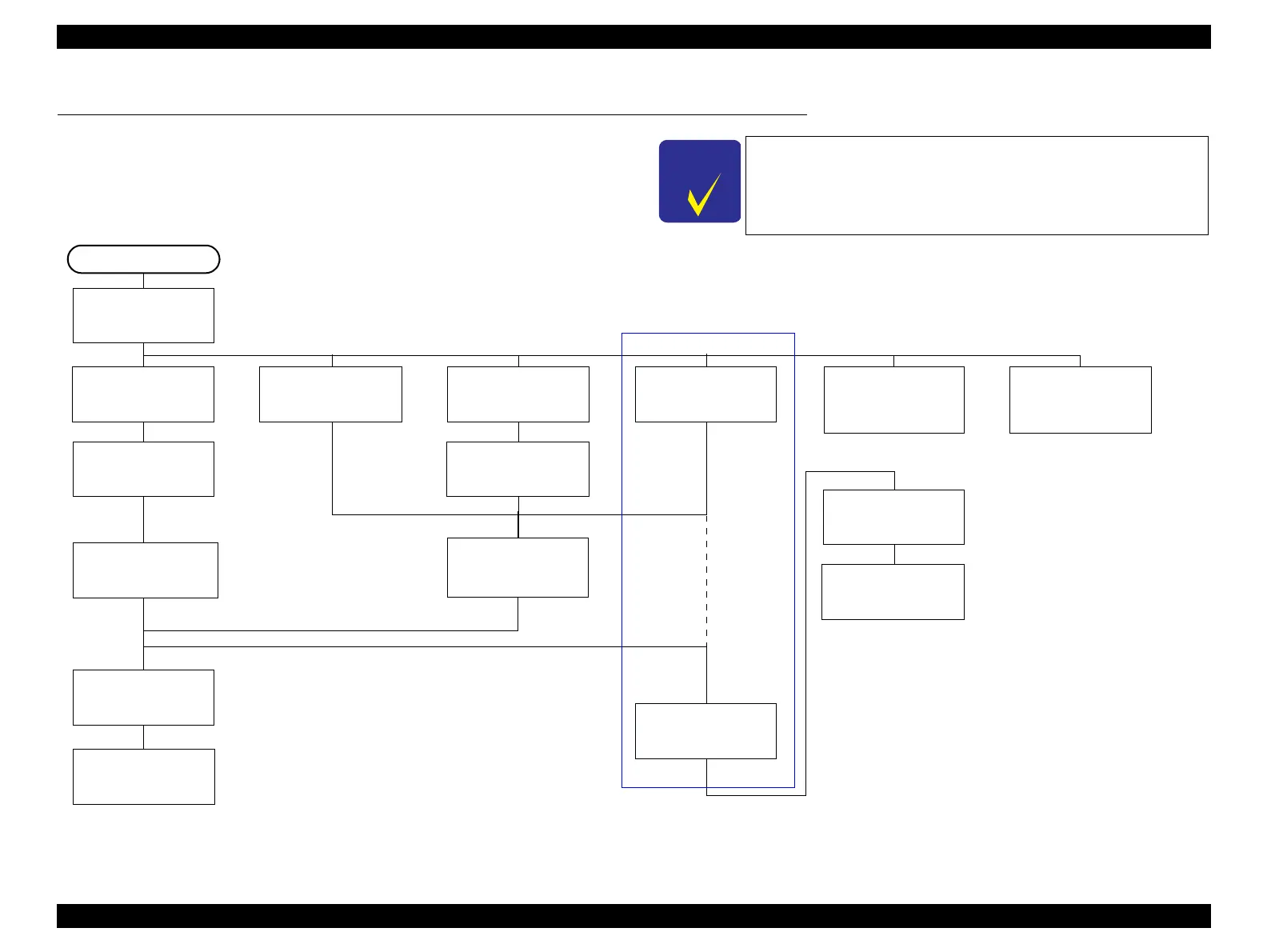
Figure 4-2. Disassembling Flowchart
Procedures partially different from model to model are described
in
“Check Point” and “Reassembly”.
Note: Shown in the dotted-line is not the
shortest procedure, but is necessary to
proceed to the next step.
“4.3.1 Upper
Housing” (p38)
“4.5.1 Hopper”
(p42)
“4.4.1 Main
Board” (p40)
*
“4.5.10 LD Roller/
ASF Unit” (p59)
“4.5.2 Printhead”
(p43)
“4.5.3 CR Scale”
(p46)
“4.5.4 CR Motor”
(p47)
“4.5.9 Main
Frame” (p56)
Ink System (Cap
Assy) (p51)
“4.5.7 Power
Supply Board”
(p53)
“4.5.8 EJ Frame
Assy/EJ Roller”
(p54)
START
*“4.5.12 PF
Roller” (p62)
*“4.5.13 PF
Motor” (p63)
*“4.5.11 Waste
Ink Pads” (p61)
*Ink System
(Pump Assy) (p51)
“4.5.6 Ink System removal” (p51)
“4.5.5 CR Unit/
Timing Belt”
(p48)
* The Shortest Way to Remove the Main Frame
If the parts to repair is the ones marked with “*” in the flowchart
only, there’s another way to remove the parts until the Main
Frame shown in the flowchart. Refer to “4.7 The Shortest Way to
Remove the Main Frame. (p. 68) ”