Epson Stylus C58/C59/ME 2/C79/D78/C90/C91/C92/D92/T20/T20E/T23/T26/S20/T10/T11/ME 30/T21/T24/T27/S21 Revision E
DISASSEMBLY/ASSEMBLY Removing Board 40
Confidential
4.4 Removing Board
4.4.1 Main Board
Part/Unit that should be removed before removing Main Board
Upper Housing /Hopper
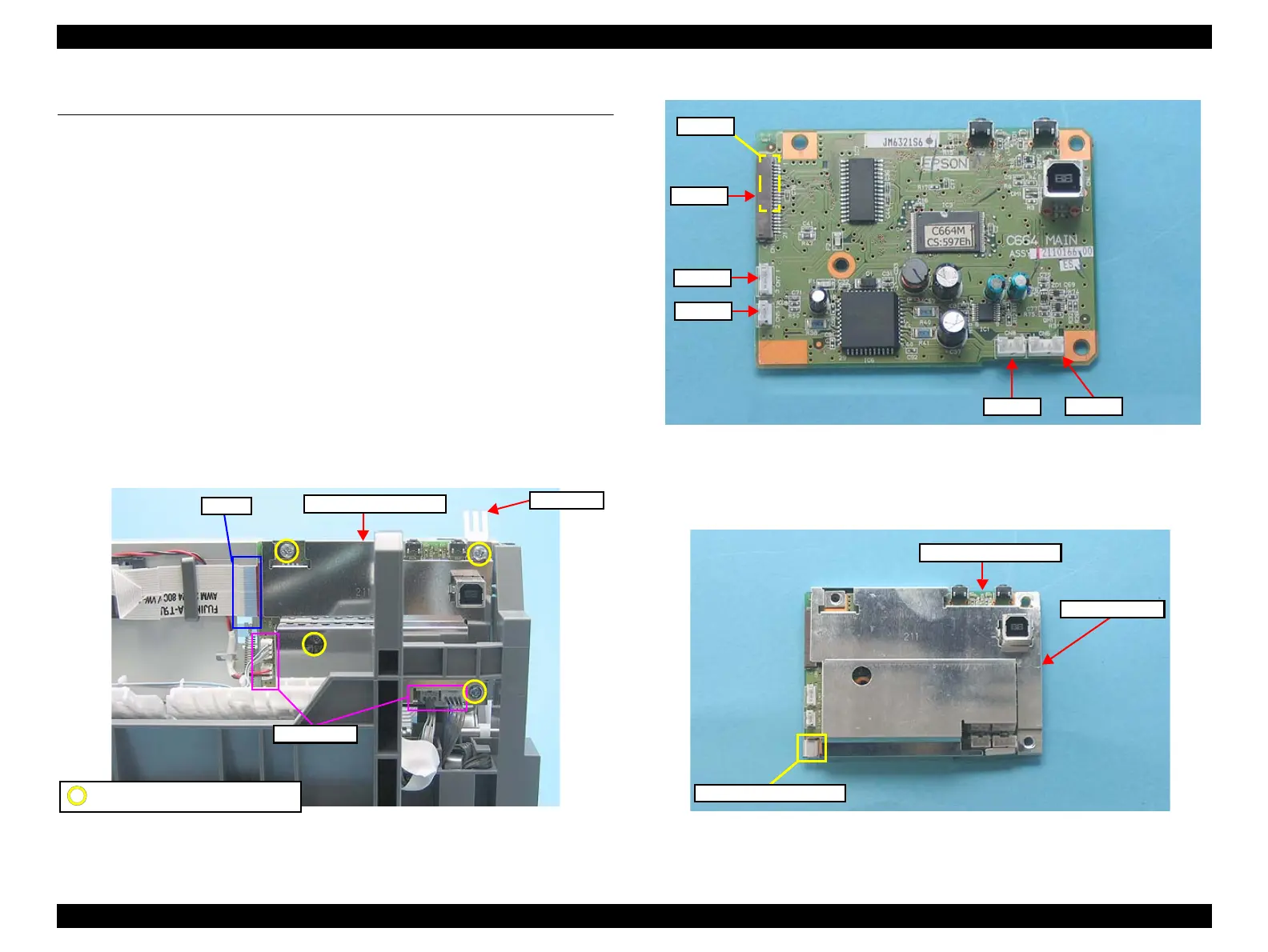
Removal Procedure
1. Peel off the acetate tapes (x2) from the Main Frame.
2. Disconnect the following connector cables (x4) and FFCs (x2) from the
connectors on the Main Board Assy.
• CN1: Head FFC
• CN3: Head FFC (Backside)
• CN5: PE Detector Connector Cable
• CN6: PF Motor Connector Cable
• CN7: CR Motor Connector Cable
• CN8: Power Supply Board Connector Cable
3. Remove the screws (x4), and remove the GND Plate M/B and the Main Board
Assy.
Figure 4-9. Removing Main Board (1)
Figure 4-10. Connector Layout of Main Board
4. Remove the Grounding Plate Clip from the Main Board Assy.
5. Remove the Shield Plate from the Main Board.
Figure 4-11. Removing Main Board (2)
FFCs
Connectors
C.B.S 3X6 (Torque: 8±1Kgf.cm)
GND Plate
Grounding Plate Clip
Shield Plate
Main Board Assy.