Epson Stylus C58/C59/ME 2/C79/D78/C90/C91/C92/D92/T20/T20E/T23/T26/S20/T10/T11/ME 30/T21/T24/T27/S21 Revision E
DISASSEMBLY/ASSEMBLY Procedure Specific to Epson Stylus C58/C59/ME 2 67
Confidential
4.6.2 Waste Ink Pads
Part/Unit that should be removed before removing Waste Ink Pads
Upper Housing /Hopper /Main Board /Main Frame /EJ Frame Assy. /
Print Head /CR Scale/CR Motor/CR Unit/Timing Belt/Ink System/Power Supply
Board/EJ Roller/ASF Unit
Removal procedure
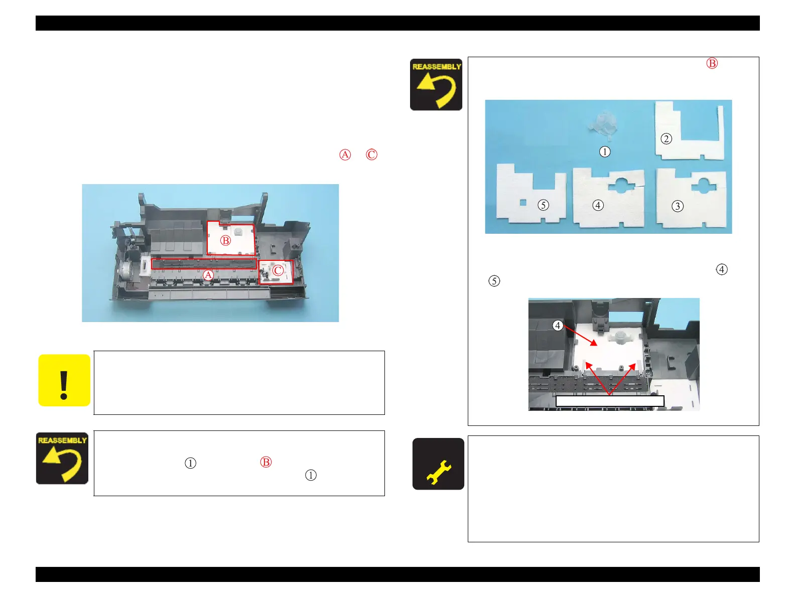
1. Remove the Waste Ink Pads (x7) from the sections indicated with to
of the Frame Base.
Figure 4-90. Removing Waste Ink Pads
When removing the Waste Ink Pads, be careful not to tear the tip
of the induction paper. If it is torn, replace the induction paper.
When installing the Waste Ink Pads, be sure to insert ribs and
tabs of the Frame Base into the slots and notches of the pads.
When installing in the section (refer to Figure 4-91), be
sure to match the positioning tabs and press until it clicks
to secure it in the right position.
When installing the Waste Ink Pads on the section , be sure
to lay the four parts one on top of another in the order shown
in the figure.
Figure 4-91. Installing Waste Ink Pads (1)
When installing the Waste Ink Pads on the section (B), make
sure to insert the tips of induction paper between the
and
pads.
Figure 4-92. Installing Waste Ink Pads (2)
A D J U S T M E N T
R E Q U I R E D
After replacing the Waste Ink Pads, perform the following
adjustment. (Refer to Chapter 5
“ADJUSTMENT”)
1. “Waste Ink Pad Counter” (only after replacement)
2. “Ink Charge”
3. “TOP Margin Adjustment”
4. “Head Angular Adjustment”
5. “Bi-D Adjustment”
6. “PF Band Adjustment”