Epson Stylus C58/C59/ME 2/C79/D78/C90/C91/C92/D92/T20/T20E/T23/T26/S20/T10/T11/ME 30/T21/T24/T27/S21 Revision E
DISASSEMBLY/ASSEMBLY The Shortest Way to Remove the Main Frame. 68
Confidential
4.7 The Shortest Way to Remove the Main Frame.
If the parts to repair is only the parts after the Main Frame is removed, there’s another
way to remove the Main Frame together with other parts. (See the following list of
“Target Parts of this removal” or the parts marked with “*” in
Figure 4-2,
"Disassembling Flowchart" (p.37))
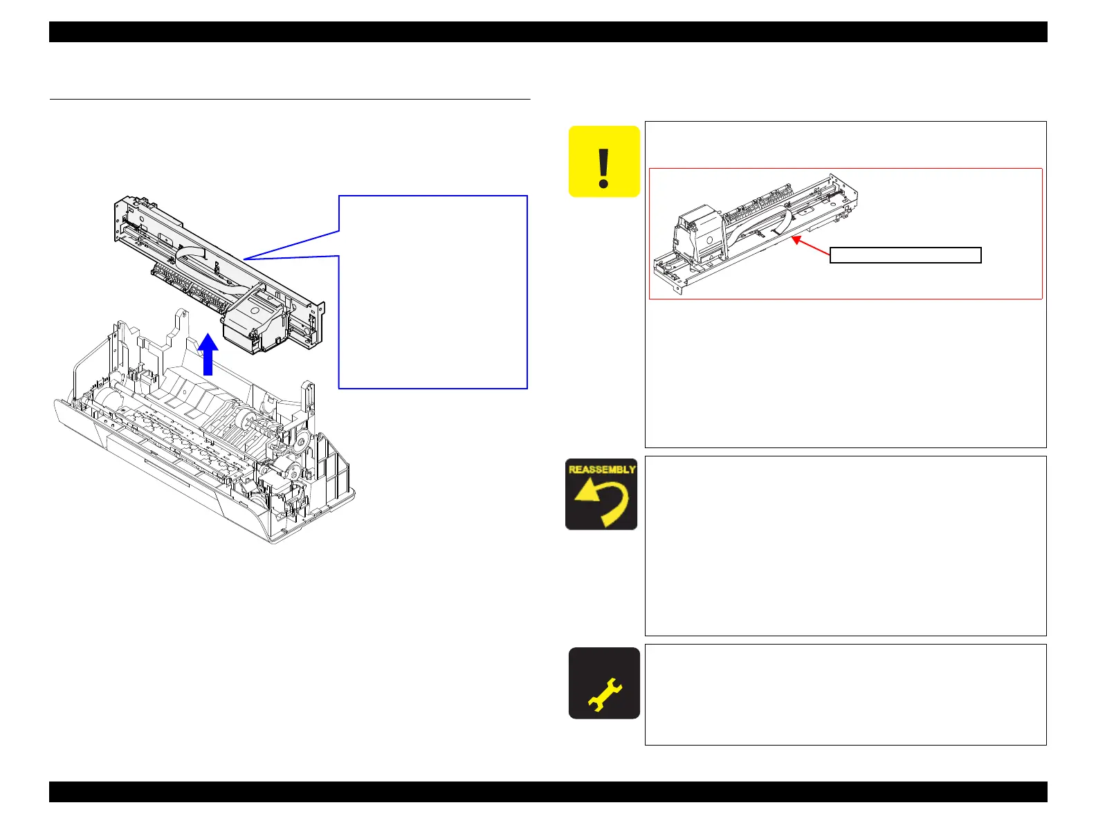
Figure 4-93. Removing Main Frame with Other Parts
Removal procedure
1. Remove the “ 4.3.1 Upper Housing ” (p.38).
2. Remove the “ 4.5.1 Hopper ” (p.42).
3. Disconnect the connector cables of P/S ASSY and PF Motor from CN6, CN8
of the Main Board. (See
“ 4.4.1 Main Board ” (p.40))
4. Remove the “ 4.5.4 CR Motor ” (p.47).
5. Remove the screw from the Shield Plate L. (The plate is not to be removed. In
Epson Stylus C79/D78’s case, see Step1 in
“ 4.5.9 Main Frame ” (p.56). In
Epson Stylus C58/C59/ME2’s case, see Check Point in “ 4.5.8 EJ Frame Assy/
EJ Roller ” (p.54))
6. Follow the same steps from Step 2 in “ 4.5.9 Main Frame ” (p.56) to Step 6.
7. Remove the Main Frame together with other parts.
LD Roller
ASF Unit
Ink System
Waste Ink Pad
PF Roller
PF Motor
Target Parts of this removal
Main Board
CR Unit
Printhead
CR Scale
Head FFC
PE Sensor
Paper Guide Upper
Main Frame with other parts
Parts removed together
After removing the Main Frame, treat and place the Main
Frame with great care while following the next instructions.
• Be careful not to deform the Main Frame.
• Do not touch or damage the nozzles or the ink supply needles
of the Printhead when placing the Main Frame.
• Be careful not to stick the grease around the area, especially
not to allow the grease to come in contact with the Timing
Belt, which can result in malfunction of the printer.
• Be careful not to lose the rollers of Paper Guide Upper, and do
not touch the rollers with bare hands.
When reassembling the Main Frame, basically follow the
removal steps backward. But in some points listed below, be
sure to refer to the reassembly instructions.
• Be careful not to bend or damage the Shield Plate L when
placing the Main Frame on the Frame Base in Step 5.
• Be careful not to damage the Carriage Lock Lever when
placing the Main Frame on the Frame Base in Step 5. (See
Preparation for LD Roller Removal (p59))
• See “ Installing Extension Springs ” (p.58) and “ Installing
Grounding Spring ” (p.58) in Step 5
A D J U S T M E N T
R E Q U I R E D
After removing the Main Frame in this removal, perform the
required adjustment. (Refer to Chapter 5
“ADJUSTMENT”)
When the Main Frame is reassembled, perform the required
lubrication. (Refer to Chapter 6
“MAINTENANCE”)
Place the Main Frame with
the back side facing down
as shown in the figure.
Figure 4-94. How to place the Main Frame
Main Frame with other parts