EPSON Stylus COLOR 440, 640, and 740 Chapter 5 Adjustments
116
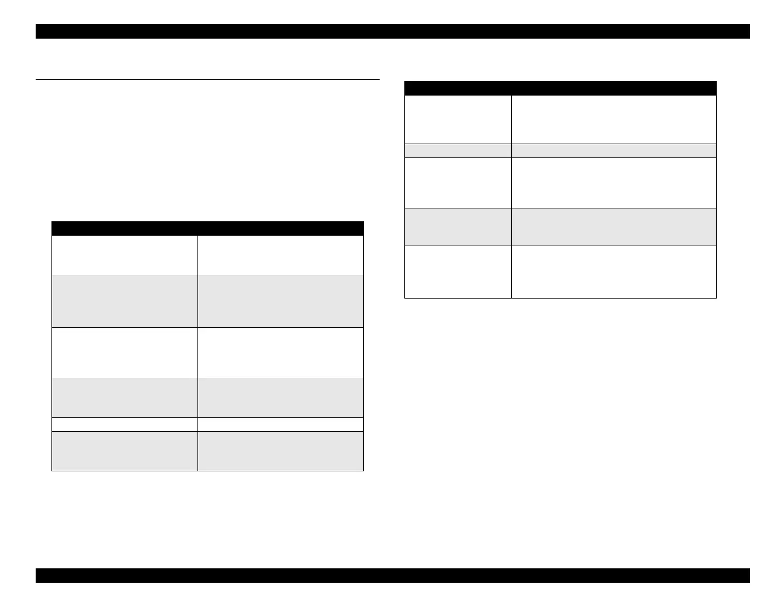
5.1 Overview
The EPSON St
lus COLOR 440, 640, and 740 re
uire certain
ad
ustments to be performed after repairin
or disassemblin
the
printer. Table 5-1 tells
ou which ad
ustments
ou must perform
followin
a
iven repair. You should follow the order of ad
ustments as
listed in the table. Table 5-2 provides the same information, but
arran
ed accordin
to the t
pe of ad
ustment.
Table 5-1 Required Adjustments
Type of Repair Required Adjustments
Removal of the printhead 1. Perform initial ink charge.
2. Perform printhead angle adjustment.
3. Perform bi-d adjustment.
Replacement of the printhead 1. Perform head voltage ID input.
2. Perform initial ink charge.
3. Perform printhead angle adjustment.
4. Perform bi-d adjustment.
Replacement of the main board 1. Perform head voltage ID input.
2. Perform bi-d adjustment.
3. Perform CG table setting (only for
Stylus COLOR 740).
Replacement or removal of the
carriage unit
1. Perform parallel adjustment.
2. Perform printhead angle adjustment.
3. Perform bi-d adjustment.
Replace of the CR motor 1. Perform bi-d adjustment.
Replacement of the printer
mechanism
1. Perform head voltage ID Input.
2. Perform initial ink charge.
3. Perform bi-d adjustment.
Table 5-2 Types of Adjustments
Adjustment When Performed
Parallelism adjustment • After removing or replacing the carriage guide
shaft
• After changing the setting of the parallelism
adjustment bushing(s)
Initial ink charge • After removing or replacing the printhead
Head voltage ID input • After replacing the printhead
• After replacing the main board
Note: The head voltage ID is not erased by the
EEPROM reset operation.
Printhead angle
adjustment
• After removing or replacing the printhead
• After moving the printhead angle adjusting
lever
Bi-d adjustment • After removing or replacing the printhead
• After removing or replacing the carriage unit
• After replacing the CR motor
• After replacing the main board

 Loading...


