EPSON Stylus COLOR 440, 640, and 740 Chapter 2 Operating Principles
56
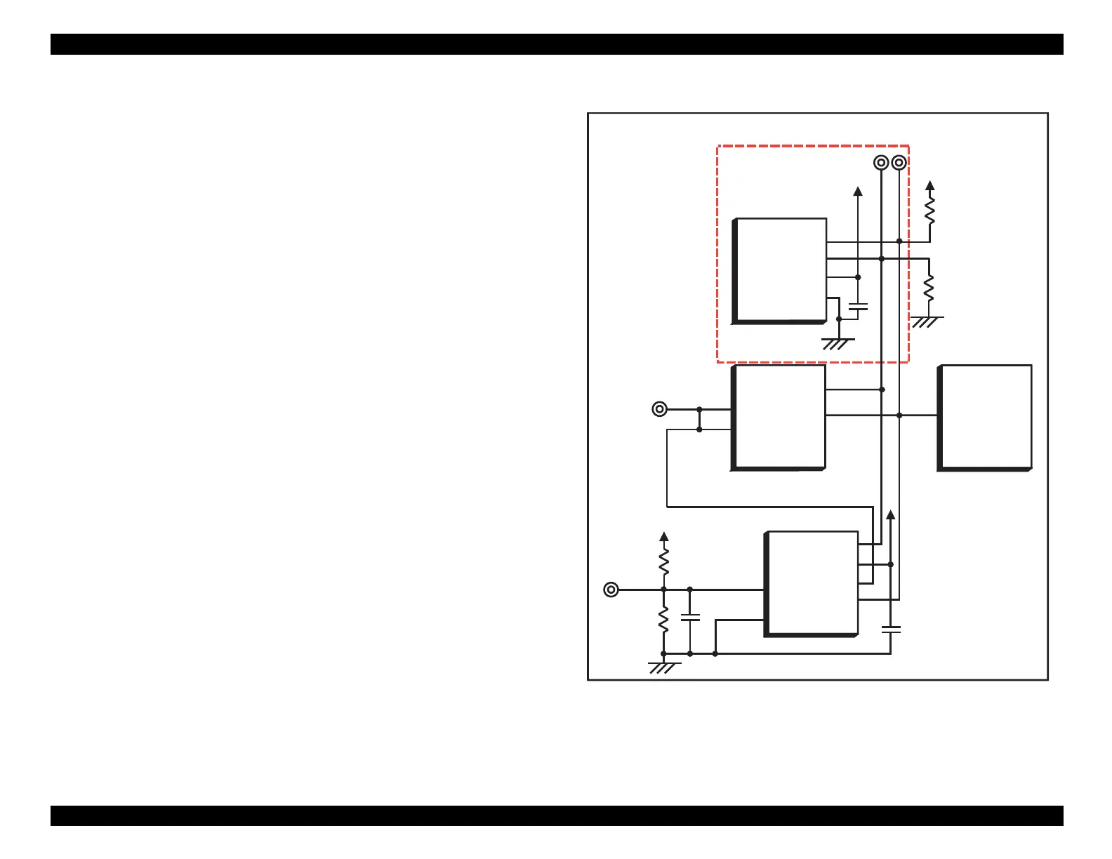
Reset Circuit
The reset circuit
IC 9 on the St
lus COLOR 440 and 640, IC8 on the
740
holds the reset pins of the CPU and the
ate arra
LOW at power-
on. This resets the chips’ internal state and prevents them from
outputtin
erratic si
nals or data. To
ive the power suppl
time to build
up a stable output volta
e, a brief dela
is built into the s
stem. This
dela
is pro
rammed b
an external RC network. When the reset si
nal
is removed after the dela
, the CPU and the
ate arra
be
in normal
functionin
.
Figure 2-23. Reset Circuit for Stylus COLOR 440
PST592D
(IC 8 )
Vcc
Vout
NRES
GND
+5V
C47
R 138
+5V
R5
/RESET
TM P95C 061
(IC 1 )
P85
E05B44
(IC 2 )
/RESET
174
30
16
1
2
3
4
M 62030
IC 9
VCC
2
4
R6
+42V
R10
+5V
MRES
OUT2
OUT1
/N M I
10
P84
15
5
6
7
8
GND
IN
N ot m ounted
G a te A rra y
CPU
Reset

 Loading...


