EPSON Stylus COLOR 440, 640, and 740 Chapter 2 Operating Principles
55
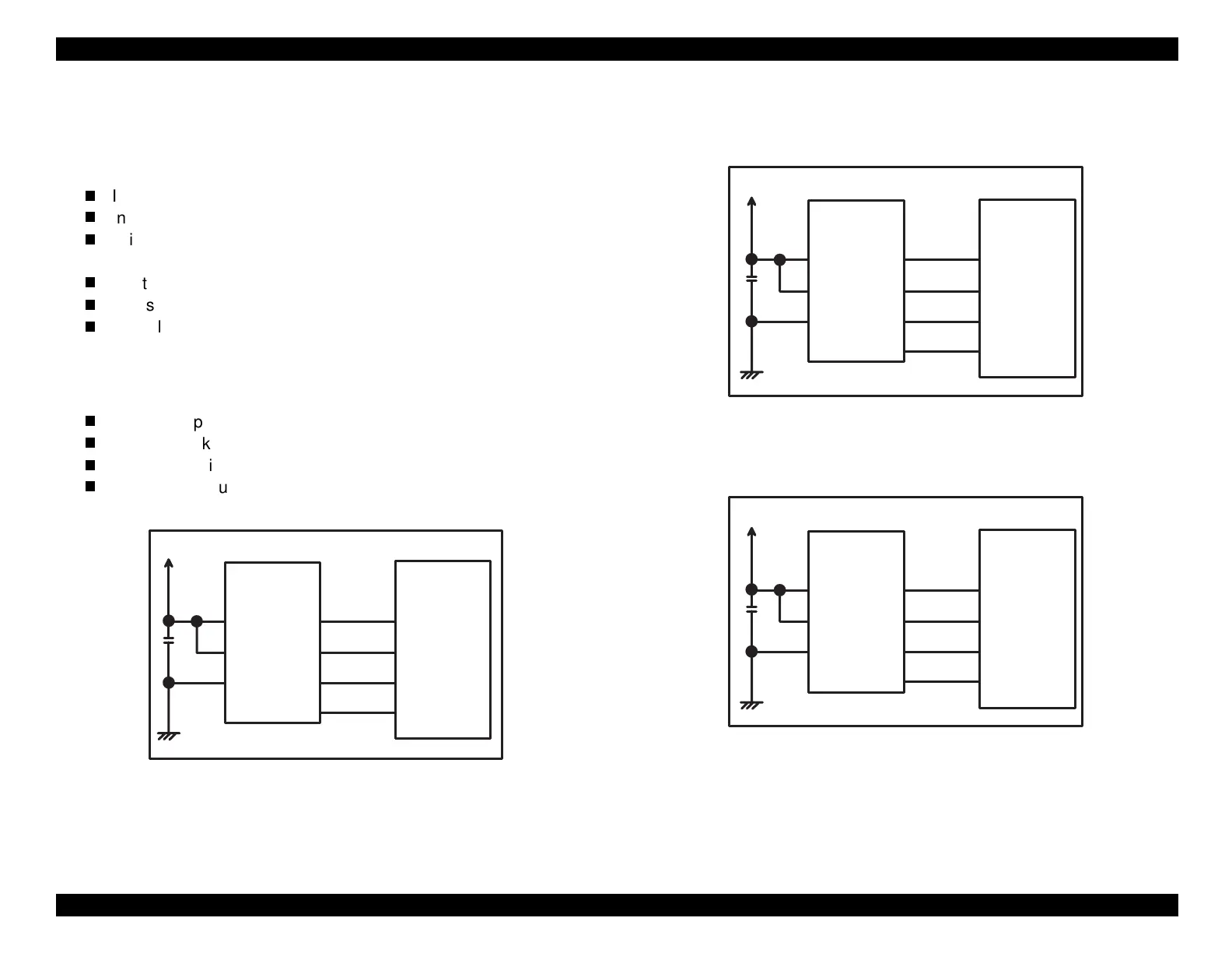
EEPROM
The EEPROM of St
lus COLOR 440, 640, and 740 contains the
followin
:
Ink cartrid
e consumption data
Blk, CMY
Ink waste pad counter
Printhead cleanin
information
keeps track of previous cleanin
operations
Destination information
Ad
ustment values
Bi-D, printhead volta
e ID, etc.
Default values set b
the user
As shown in the fi
ures below, the EEPROM connects to the
ate arra
IC2
b
4 lines which perform the followin
functions:
CS: Chip select si
nal
CK: Clock pulse
DI: Data in
writin
of serial data at power off
DO: Data out
readin
of serial data at power on
Figure 2-20. EEPROM Control Circuit for Stylus COLOR 440
Figure 2-21. EEPROM Control Circuit Stylus COLOR 640
Figure 2-22. EEPROM Control Circuit for Stylus COLOR 740
+5V
8
6
5
AT93C 46
(IC 1 1 )
Vcc
GND
ORG
E05B 44
(IC 2 )
127
128
126
125
1
2
3
4
CS
CK
DI
DO
ECS
ECK
ECO
ECI
+5V
8
6
5
AT93C 46
(IC 11)
Vcc
GND
ORG
E05B 43
(IC 2 )
130
129
128
127
1
2
3
4
CS
CK
DI
DO
ECS
ECK
ECO
ECI
+5V
8
6
5
AT93C 46
(IC 7 )
Vcc
GND
ORG
E05B 588
(IC 2 )
206
205
204
203
1
2
3
4
CS
CK
DI
DO
EECS
EECK
EECO
EECI

 Loading...


