EPSON Stylus COLOR 440, 640, and 740 Chapter 4 Disassembly and Assembly
88
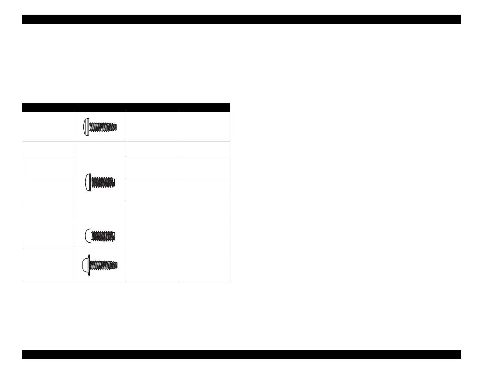
4.1.3 Specification for Screws
Table 4-2 shows screw specifications. Durin
assembl
, make sure to
insert the correct screw at each location. Note that the screw numbers
referred to in the manual
e.
., “#1”
correspond to the numbers of the
screw t
pes shown in the table, not to screw sizes.
Table 4-2. Screw Characteristic
Type Number Body Name Size
1 Cross bind-head,
S-tight
M3
×
6
2 Cross bind-head,
S-tight
M3
×
10
3 Cross bind-head,
P-tight
(CBP tight)
M3
×
6
4 Cross bind-head,
P-tight
(CBP tight)
M3
×
10
5 Cross bind-head,
P-tight
(CBP tight)
M3
×
8
6 Cross pan-head
(CP)
M3
×
4
7 Cross bind-head,
S-tight, Sems
R2 (CBS Sems)
M3
×
6

 Loading...


