EPSON Stylus COLOR 440, 640, and 740 Chapter 3 Troubleshooting
68
3.1 Troubleshooting
The printer ma
exhibit different s
mptoms for the same problem. Start
with
Table 3-4
to locate the appropriate flowchart, and then use the
flowchart to identif
a problem based on its s
mptoms. Refer to the
tables at the end of this chapter for detailed information on testin
and
repairin
printer components.
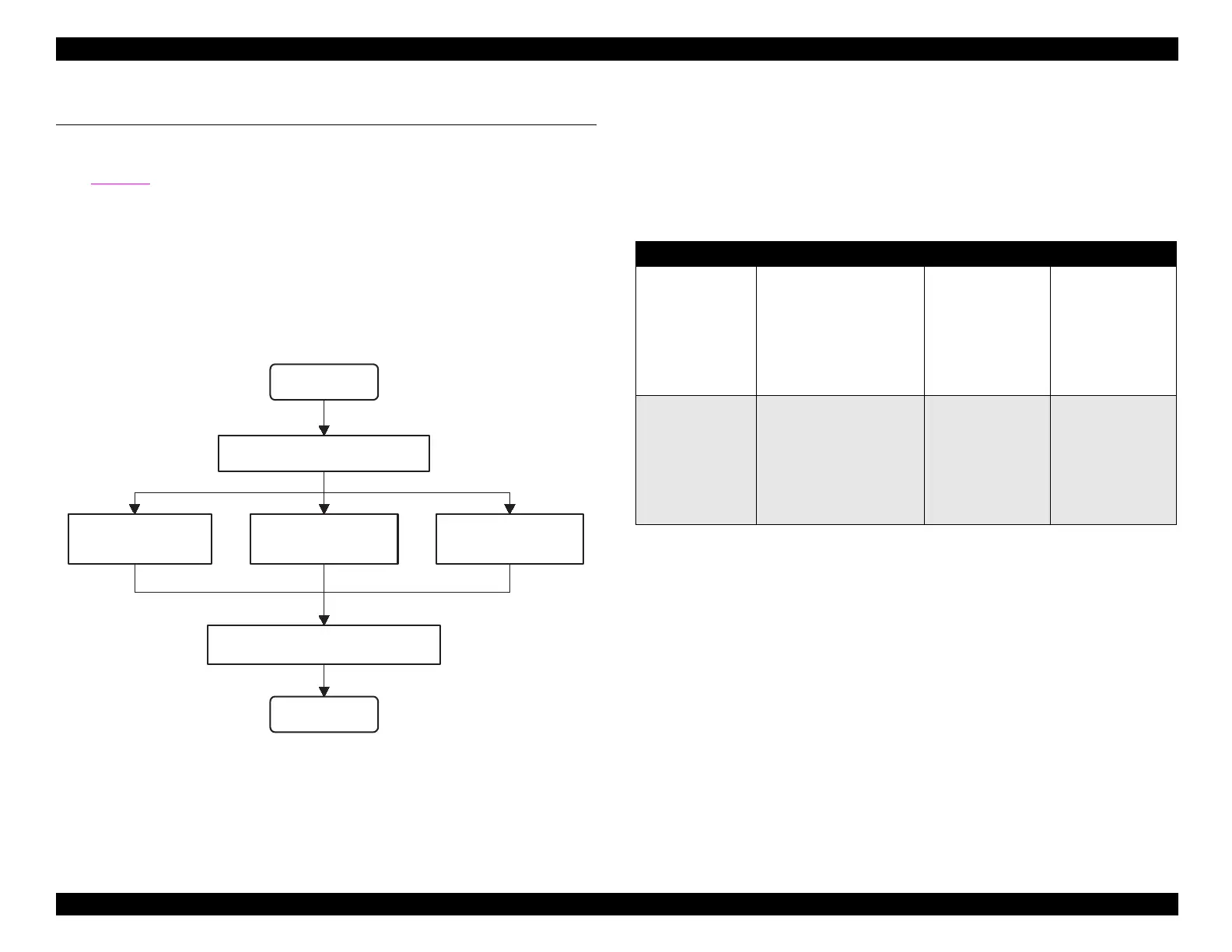
The followin
fi
ure illustrates the main steps of the troubleshootin
process.
Fi
ure 3-1. Troubleshootin
Process Flowchart
3.1.1 Component Test Specifications
The followin
tables specif
the values at which the CR motor, PF
motor, and sensors should test. In addition, Table 3-3 shows how to
interpret the printer’s LED error indicators.
Table 3-1. Motor Coil Resistance
* Main board refers to the following:
Stylus Color 440: C206 Main-B or C255 Main
Stylus Color 640: C256 Main
Stylus Color 740: C257 Main
START
END
Unit-Level Troubleshooting
Power Supply
Repair
Main Board
Repair
Reassembly and Adjustment
Printer Mechanism
Repair
Motor Name Location Check Point Resistance
CR motor • St
lus Color 440/
640 CN6
Main
board *
•St
lus Color 740
CN7
Main board
*
Pins 1 & 3,
Pins 2 & 4
7.8 Ohms
±
10%
PF
pump
motor
•St
lus Color 440/
640 CN7
Main
board *
•St
lus Color 740
CN8
Main board
*
Pins 1 & 3,
Pins 2 & 4
7.8 Ohms
±
10%

 Loading...


