EPSON Stylus COLOR 440, 640, and 740 Chapter 2 Operating Principles
48
2.2 Electronic Circuit Boards
The St
lus COLOR 440, 640, and 740 contain three circuit boards each:
St
lus COLOR 440:
Main: C206 Main-B or C255 Main Board *
Power Suppl
: C206 PSB, PSE Board
Control Panel: C206 PNL Board
St
lus COLOR 640:
Main: C256 Main Board
Power Suppl
: C206 PSB, PSE Board
Control Panel: C206 PNL Board
St
lus COLOR 740:
Main: C257 Main Board
Power Suppl
: C257 PSB, PSE Board
Control Panel: C209 PNL Board
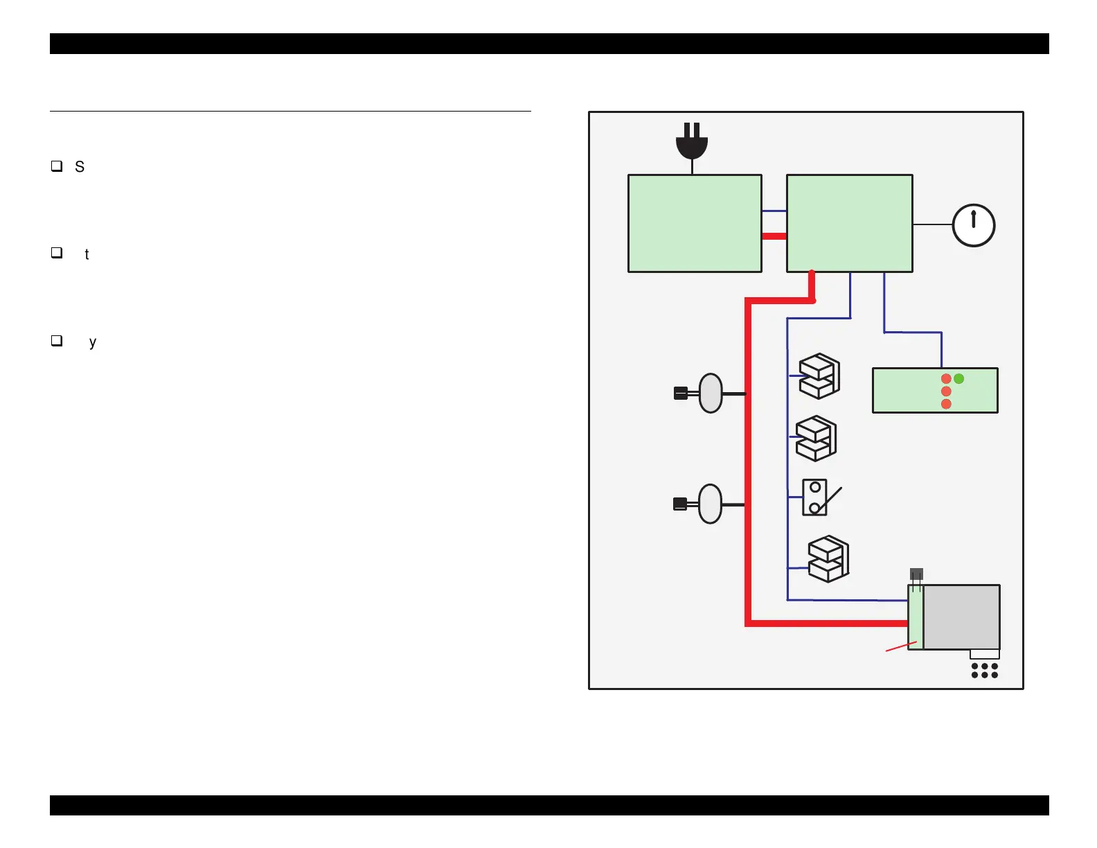
The printer’s main electrical s
stems are connected as shown in Fi
ure
2-15 at ri
ht.
* The C255 Main board will eventuall
replace the C206 Main-B board.
Figure 2-15. Connections Between Main Electrical Systems
PF M otor
CR Motor
C206 PSB/PSE Board
C257 PSB/PSE Board
+5 V D C
AC Input
Ink-End Counter
and Pow er-O ff
Tim er
PE Sensor
Black/C olor Ink Cartridge Sensor
ASF Lever
Position Sensor
Printhead
+42 V D C
N ozzle S elector
HP Sensor
Therm istor
12
6
3
9
1
2
4
5
7
8
10
11
C206 M ain-B
C255 M ain
C256 M ain
C257 M ain
+5 V D C
+42 V D C
C206 PNL
C209 PNL
LE D
+5 V D C

 Loading...


