EPSON Stylus COLOR 440, 640, and 740 Chapter 2 Operating Principles
50
volta
e, the power suppl
’s cost is reduced.
Althou
h a small
transformer is still used, it’s relativel
inexpensive compared with the
lar
e, heav
transformer that would otherwise be needed.
The RCC switchin
circuit works b
alternatel
ener
izin
and de-
ener
izin
the transformer. Oscillation be
ins when the volta
e at the
ate of Q1 rises throu
h kick-start resistor R18. Current passin
throu
h Q1 enters transformer T1, ener
izin
its primar
coils. Since
diode D51 prevents current from flowin
throu
h the transformer’s
secondar
coils, the transformer is forced to store the ener
as a
ma
netic field.
After startup, Q1 is held b
volta
e supplied b
the transformer. This
volta
e is switched on and off b
IC1, a pro
rammable uni
unction
transistor
PUT
. As the transformer becomes ma
neticall
saturated,
its output volta
e drops below the PUT’s holdin
threshold, and the
PUT shuts off. This deprives Q1 of volta
e, causin
it to shut off and
allowin
the transformer to release its stored ener
. As the ma
netic
field collapses, current be
ins flowin
throu
h the transformer’s
secondar
coils.
Since the current’s direction is reversed durin
dischar
e, diode D51 no lon
er blocks its flow.
When the transformer
has full
de-ener
ized, the c
cle repeats. The resultin
pulsed output
contains less ener
than the ori
inal input, since the unwanted ener
has been chopped out, and can now be used for the final stepped-down
volta
e. To smooth the waveform, capacitor C51 filters the output,
which is then re
ulated at 42 volts b
a stack of seven 6-volt zener
diodes.
As discussed above, the power suppl
contains a built-in dela
that
enables the printer to remain on lon
enou
h to complete its power-
down operations. When
ou turn on the printer b
pressin
the power
switch on the front control panel, the power control si
nal
PSC
from
the main board ener
izes transistor Q84, which acts as a rela
and
turns on the power suppl
. At the same time, the PSC char
es
capacitor C84. As a result, even when
ou shut the printer off, the
capacitor continues suppl
in
power to Q84 and keeps the printer on for
at least an additional 30 seconds.
To protect the printer, the power suppl
incorporates over-volta
e,
under-volta
e, and short-circuit protection circuitr
. These circuits
contain zener diodes, which monitor the re
ulated output volta
es. If
the 5-volt suppl
exceeds 9 volts, or if the 42-volt suppl
exceeds 48
volts, the RCC switchin
circuit is immediatel
shut off and its output
falls to zero. In addition, a volta
e drop protection circuit protects the
printer in case of a short circuit in an
component that draws from the
42-volt line. This also works b
shuttin
off the switchin
circuit, which
occurs when output falls below 36 volts. Finall
, fuse F1 protects the
power suppl
itself, in case of a short circuit in an
primar
component.
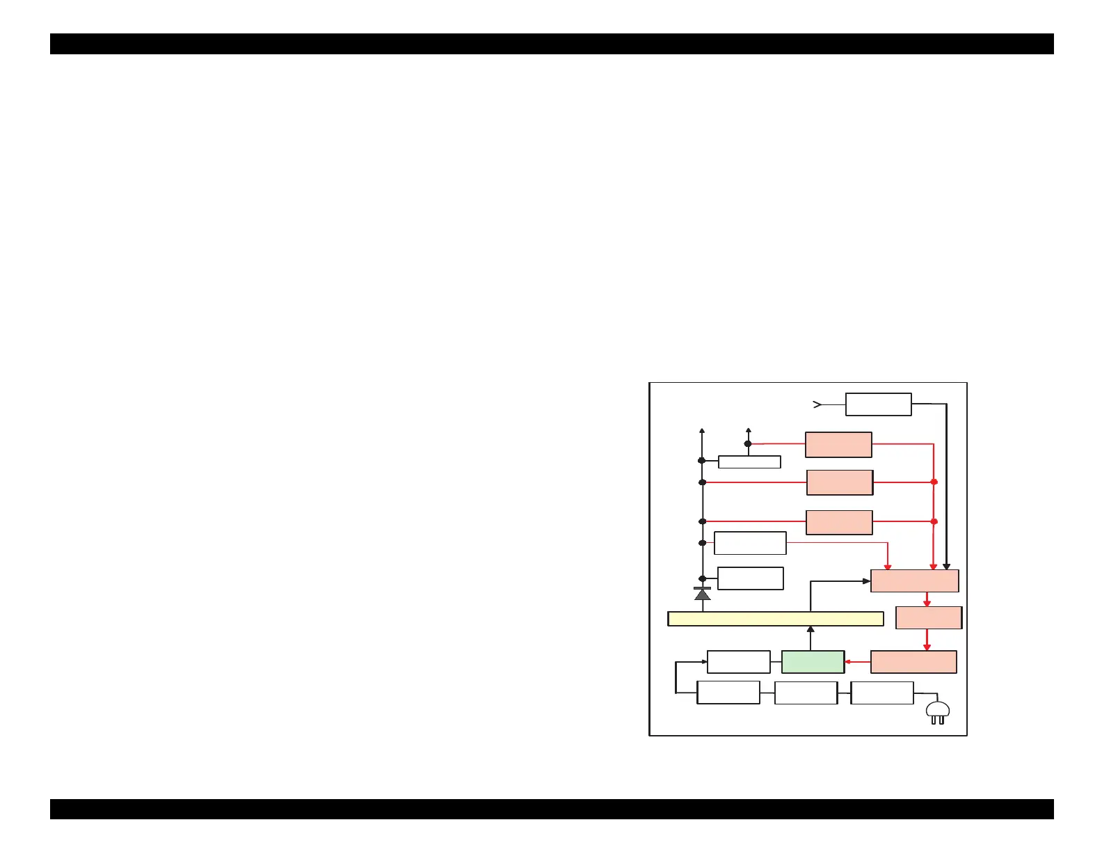
Figure 2-16. PSB, PSE Board Block Diagram
F1
C11
L1,R1-2
C1-C4
DB1
Transformer (T1)
Fuse
Filter Circuit
Bridge
Rectifier
Smoothing
Capacitor
Main Switching
Transistor
Q1
Feedback circuit
Q2,Q3,Q31
Photo-
Coupler
PC1
D51
AC Input
Smoothing
Capacitor
C51
+42VDC Line
Voltage Regulator
ZD81-86,ZD51
Power Drop
Delay Circuit
C84,Q84
+42VDC Line
Over-Voltage
Monitor
ZD52,87
+5V Regulator
IC51
+42 VDC
+5 VDC
+5VDC Line
Over-Voltage
Monitor
PSC
ZD53
+42VDC Line
Under-Voltage
Monitor
ZD90
Feedback circuit

 Loading...


