EPSON Stylus CX3500/CX3600/CX3650/CX4500/CX4600 Revision A
DISASSEMBLY AND ASSEMBLY Disassembly 153
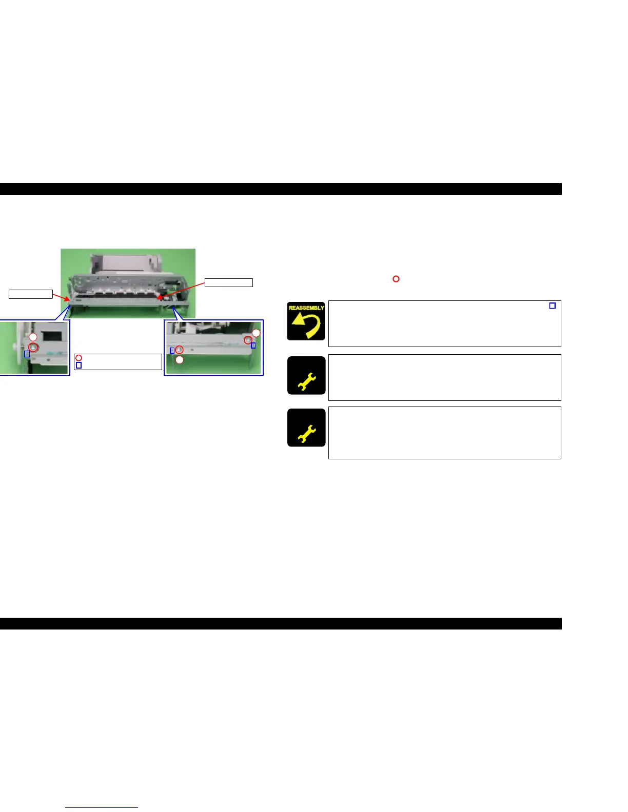
4.3.19 Front Frame
V External View
Figure 4-43. Front Frame Removal
V Part/Unit that should be removed before removing Front Frame.
Document Cover / Paper Support Assy. / Scanner Unit / Panel Unit /
Housing Upper / Print Head/ Printer Mechanism / Main Board Unit /
CR Guide Frame / CR motor / Carriage Unit
V Removal procedure
1. Remove the screws (x3, ) for securing Front Frame, and then remove Front
Frame from Printer Mechanism.
2
1
3
Front Frame
C.B.S 3x6 F/Zn (7±1kgfcm)
Ribs
EJ Frame Unit
T Align the positioning holes of Front Frame with the ribs (x3, )
of Main Frame.
T Tighten the screws in order shown by figure.
ADJUSTM ENT
REQUIRED
When changing the Front Frame for new one, always apply grease
KEN to the specified portion.
T Refer to Chapter 6, Figure 6-10 (p.179)
ADJUSTM ENT
REQUIRED
When having removed or replaced Front Frame, implement the
adjustment in the following order. (Refer to Chapter 5
“ADJUSTMENT”)
1. Bi-D adjustment
2. First dot adjustment
 Loading...


