EPSON Stylus CX3500/CX3600/CX3650/CX4500/CX4600 Revision A
ADJUSTMENT Adjustment Except Adjustment Program 173
17. Accede to following steps to check left side PG again.
Figure 5-16. Right/Left Sides PG Checking
18. Tighten both screws completely.
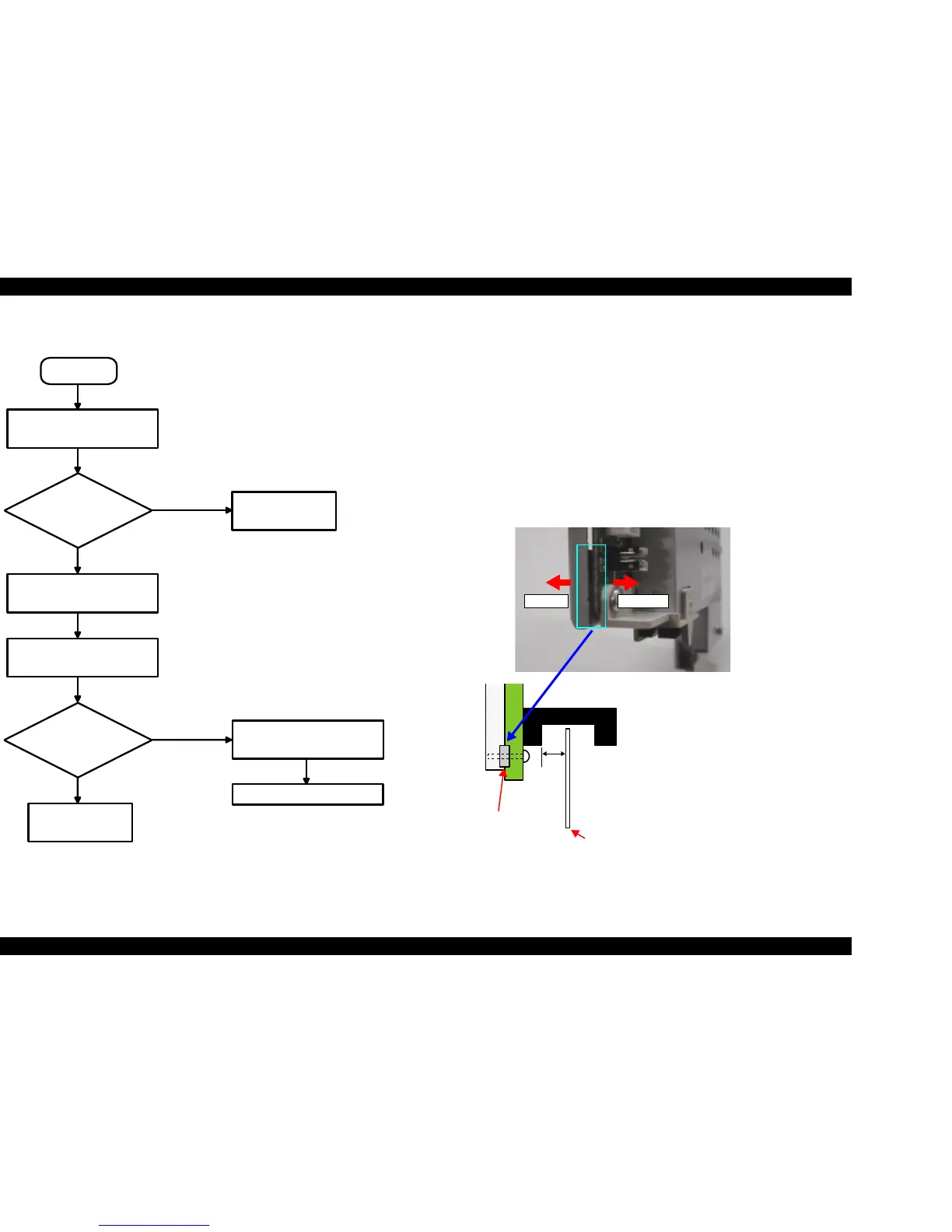
5.3.2 PF Scale Sensor positioning adjustment
V Parts to be Removed and Replaced
T Replacement of Main Board Unit
T Replacement of PF Roller Unit
V Adjustment procedure
1. Test fit Main Board Unit, and confirm whether or not PF Scale is positioned
in the center of PF Sensor.
2. If PF Scale is positioned in the center of PF Sensor, adjustment is complete. If
scale is not positioned in center of sensor, adjust position of PF Scale using
spacer (0.5mm thickness) as shown in diagram below.
Figure 5-17. PF Scale Sensor positioning adjustment
START
Move the Carriage Unit by
using the Timing Belt.
Thickness Gauge
moves?
One notch up the Parallel
Adjustment Lever (Left).
Move the Carriage Unit by
using the Timing Belt.
Thickness Gauge
moves?
Re-adjust from
the beginning.
One notch down the Parallel
Adjustment Lever (Left).
Advance to Step 18.
Yes
Yes
No
Note : “Up” means PG (Platen Gap) narrow.
Note : “Down” means PG
(Platen Gap) wide.
No
Re-adjust from
the beginning.
Left side Right side
0.1 to
1.0mm
Spacer
PF Scale
Spacer is not applied to Main
Board Unit for service part.
T Place spacer between Shield
Board and Main Board.
T If PF Scale is off to the left,
remove the spacer.
T If PF Scale is off to the right,
add an additional spacer.
(Total of 2 spacers)
 Loading...


