EPSON Stylus CX3500/CX3600/CX3650/CX4500/CX4600 Revision A
OPERATING PRINCIPLES Electrical Circuit Operating Principles 70
2.4 Electrical Circuit Operating Principles
The electric circuit of the Stylus CX3500/CX3600/CX3650/CX4500/CX4600 consists
of the following boards.
V Main Board (CPU-ASIC 2 in 1 + Soldering Flash ROM)
T Stylus CX3500/CX3600/CX3650 : C577 Main Board
T Stylus CX4500/CX4600 : C571 Main Board
V Power Supply Board : C571 PSB/PSE Board
NOTE: CPU and ASIC is integrated as one chip (IC8) on the Main Board.
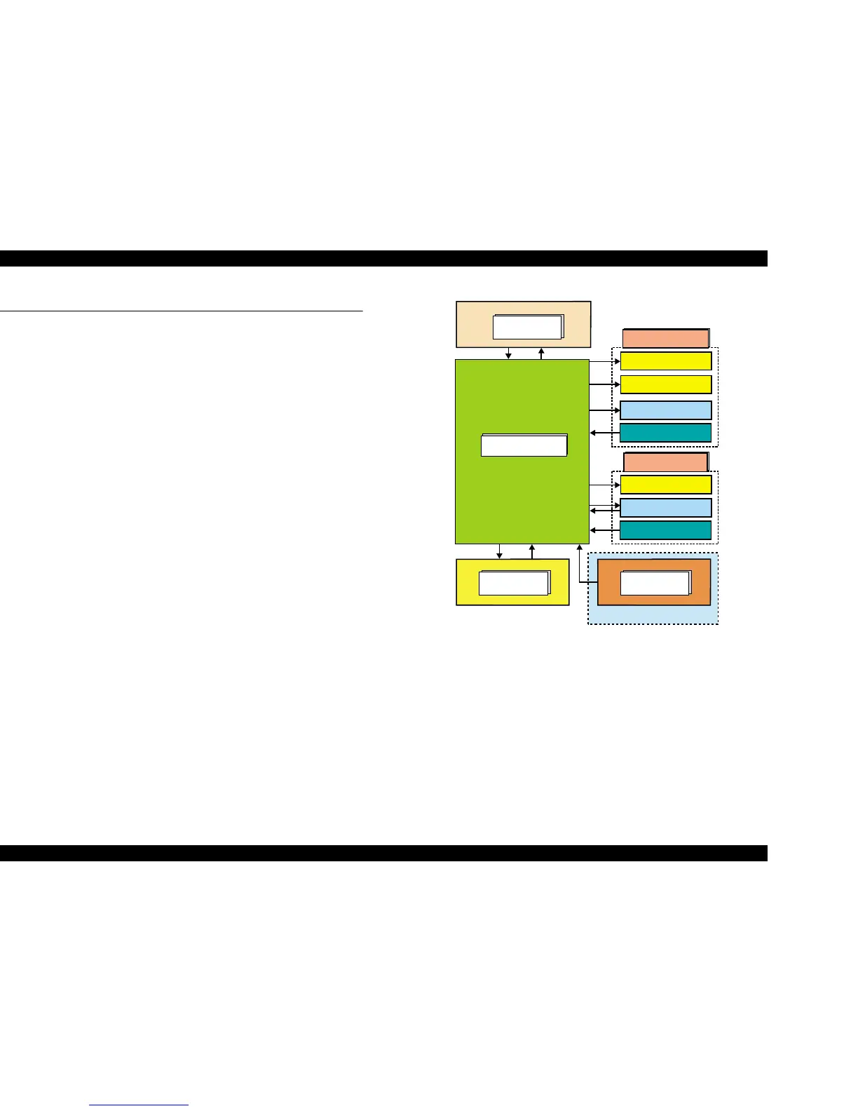
This section provides operating principles of C577 Main Board, C571 Main Board and
C517 PSB/PSE Board. Refer to Figure 2-17 (p.70) for the major connection of the each
boards and their roles.
Figure 2-17. Electric circuit
C577/C571
Main Board
C571 PSB/PSE
Board
Sensors
Head Driver Board
PF Motor
CR Motor
Printer Mechanism
+42VDCPower Off
C577 PNL Board
Scanner Mechanism
Scanner Motor
CIS Unit
Scanner HP Sensor
Memory Card
Note: Only for C571 Main Board
 Loading...


