EPSON Stylus CX3500/CX3600/CX3650/CX4500/CX4600 Revision A
DISASSEMBLY AND ASSEMBLY Disassembly 157
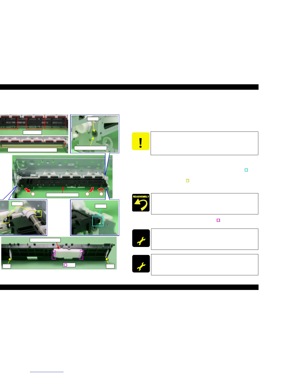
4.3.22 Paper Guide Front Unit
V External View
Figure 4-48. Paper Guide Front Unit Removal
V Part/Unit that should be removed before removing Paper Guide Front Unit.
Document Cover / Paper Support Assy. / Scanner Unit / Panel Unit /
Housing Upper / Print Head/ Printer Mechanism / Main Board Unit /
ASF Unit / Holder Shaft Unit / CR Guide Frame / CR motor / Carriage Unit /
Front Frame / EJ Frame Unit / Ink System Unit
V Removal procedure
1. Remove Plain Washer (x1) for securing Paper Guide Front Unit by using the
tweezers, remove Paper Guide Front Unit from Main Frame.
2. Shift Paper Guide Front Unit to the left until releasing the dowel (x1, ) from
the installation hole of Main Frame.
3. Release the left dowels (x2, ) of Paper Guide Front Unit from the
installation holes of Main Frame while lowering the right end of Paper Guide
Front Unit.
4. Remove Waste Ink Pad Lower from the ribs (x4, ) at the bottom surface of
Paper Guide Front Unit.
Paper Guide Front Unit
12
3
Plain Washer 2.6x0.5x8
Dowel
Dowel
Dowels
Waste Ink Pad Lower
Ribs
Tab Tab
PF Roller Unit Coating Location
Rib Surface
CAUTION
T Be cautious of the following points when performing the next
steps.
• Do not damage the ribs of Paper Guide Front Unit surface.
• Do not cause damage by touching the coating location of PF
Roller Unit.
T Confirm that the tabs (x2) of Paper Guide Front Support Porous
Pad face inward.
T If ink has spread to the ribs on the upper surface of Paper Guide
Front Unit, use a cotton swab to remove it.
ADJUSTM ENT
REQUIRED
After changing the Paper Guide Front Unit for a new one, always
apply grease G-26 to the specified portions.
T Refer to Chapter 6, Figure 6-9 (p.179)
ADJUSTM ENT
REQUIRED
When having removed or replaced Paper Guide Front Unit,
implement the adjustment in the following order. (Refer to Chapter
5 “ADJUSTMENT”)
T Bi-D adjustment
 Loading...


