QX5
QXFXO4/QXISDN4/QXE1T1/QXFXS24; (SW Version 6.0.x) 40
QXFXO4/QXISDN4/QXE1T1/QXFXS24 Manual II: Administrator’s Guide
Non Automat
checkbox switches to non-automatic Terminal
Endpoint Identifier (TEI) searching and enables the
TEI Address
field that requires a TEI number (digit values from 0 to 63) for
connection establishment between CO and E1/T1 client. In automatic
mode, an E1/T1 connection will be established on the first available
TEI, while in non-automatic mode a specific TEI may be reserved for
the connection. In this case both call partners need to specify the
same TEI in their settings.
The SAPI Value text field requires an additional Service Access Point
Identifier (SAPI) value (digit values from 1 to 62) that is used to
support additional interface between ISDN Layer 2 and Layer 3.
Leaving this field empty (default value), only Call Control and Layer 2
management procedures will be activated.
When Alternative Disconnection Mode checkbox is not selected, QX
will disconnect the call as soon as disconnect message has been
received from the peer, otherwise, when checkbox is selected, QX's
user may hear a busy tone when peer has been disconnected.
In the Network Mode (PBX connected):
• If Non Automat mode is selected, the same TEI address
should be specified on both sides- QX and PBX.
• If Automat mode is selected the user on PBX side will
have the opportunity to set any mode related to TEI
assignment in PBX configuration. This will allow PBX
connection to the QX without providing the TEI address
from QX.
In the User Mode (CO connected) the TEI assignment is dependent
on CO settings:
• Select Non Automat mode and insert the same TEI
address provided by CO.
• Select any mode related to TEI assignment if automat TEI
searching mode is selected on CO side.
Two groups of timers need to be provided. These settings are
adjusted according to the Service Provider requirements.
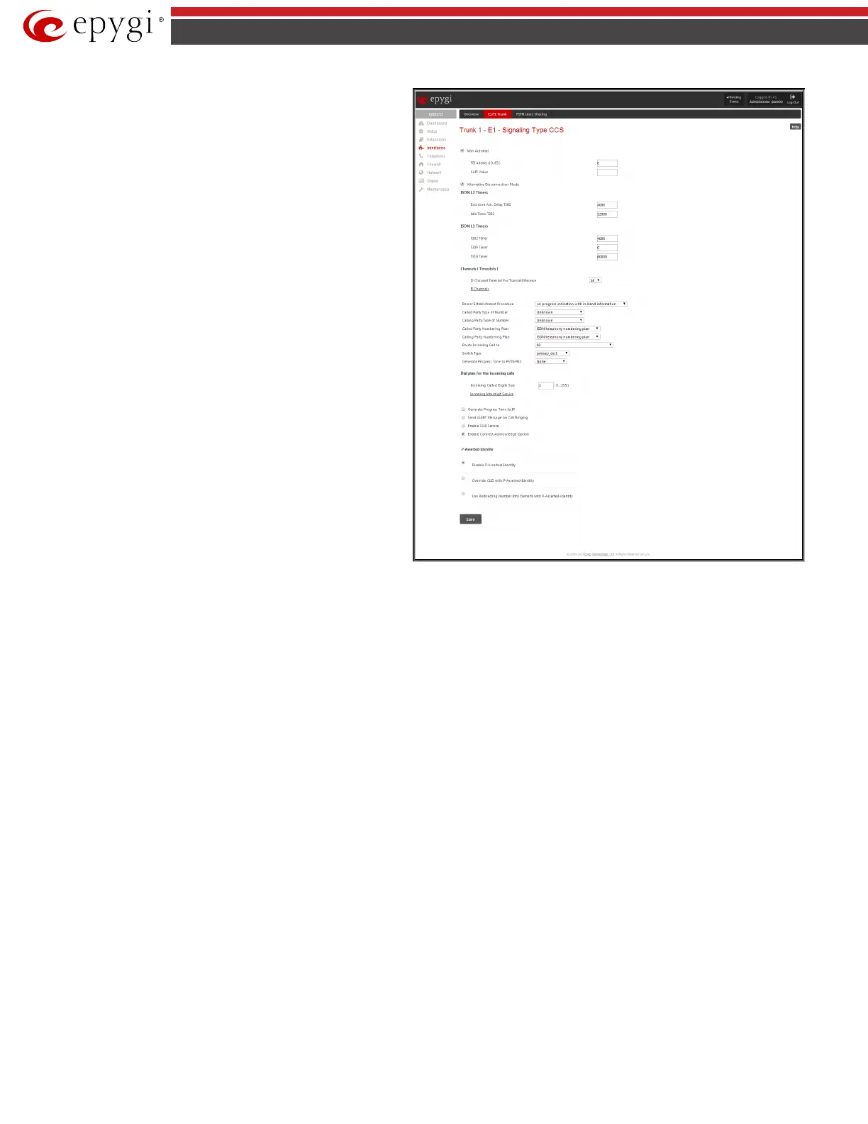
Fig.II- 48: Trunk CCS Signaling Settings page
ISDN L2 Timers:
• The Excessive Ack. Delay T200 text field configures the period in milliseconds (digit values from 500 to 9999) between transmitted signaling
packet and its acknowledgement received.
• The Idle Timer T203 text field configures the period in milliseconds (digit values from 1000 to 99999) for E1/T1 client idle timeout.
ISDN L3 Timers:
• The T302 Timer text field requires the value for the T302 timer in milliseconds (digit values from 0 to 15000) and indicates the time frame
system is waiting for digit to be dialed and when timer expires, it initiates the call. Timer is not applicable for DMS-100 switch types.
• The T309 Timer text field requires the value for the T309 timer in milliseconds (digit values from 0 to 90000) responsible for call steadiness
during link disconnection within the period equal to this timer value. If the value in this field is 0, T309 timer will be disabled.
• The T310 Timer text field requires the value for the T310 timer in milliseconds (digit values from 1000 to 120000) responsible for the
outgoing call steadiness when CALL PROCEEDING is already received from the destination but call confirmation (ALERT, CONNECT, DISC or
PROGRESS) is not yet arrived.
The D Channel Timeslot For Transmit/Receive drop down list contains the timeslots to be selected for signaling data transmit/receive.

 Loading...

