Site Configurations, RBS 2000 Micro
2 Site Configurations, RBS 2000 Micro
2.1 Terminology
AC box The AC box splits the incoming mains to
the site to different AC users in the site.
This is external equipment that is
delivered by the local support organization
in each country or region.
Interfaces There are a number of interfaces in the
system: AC mains, DC 24 V, DC –48 V,
External alarms, Alarms, Data,
Transmission, T,X,L-bus, RF Feeders
N/A Not Applicable
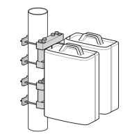
Mini Link E-micro Mini Link E-micro is a transmission unit
that sends transmission via the radio
interface.
MLPU Mini Link Lightning Protection Unit
PBC Power Battery Cabinet
The PBC converts AC mains to 24 V and
–48 V. It includes battery backup for RBS
and AAU.
R1P1A1RL1PL1AL1/M1 Configuration with: 1 RBS, 1 PBC, 1
AAU, 1 RLPU, 1 PLPU, 1 ALPU and
optional 1 Mini Link
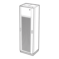
RBS 2302 RBS 2302 is a radiobasestation based on
the RBS 2301. It is developed for 6 TRX
functionality and prepared for MAXITE
TM
installations.
t
ext
means External temperature
2.2 System Overview
2.2.1 Site Configurations Overview
The tables below describe the different site configurations for RBS 2302
products.
Fan units and Mini Link configurations are considered to be optional
and therefore marked with a “slash” ( / ), for example “/RF1” or ”/M1”).
Table 2 RBS 2302 Site Configurations
Short no. Slogan RBS 2302 PBC Fan Unit Mini Link
(R) (P) (RF,PF) (M)
R1 2 TRX 1 /RF1
R2 4 TRX 2 /RF2
EN/LZT 123 2697 R5A
1998-08-13
15 (306)
© Ericsson Radio Systems AB
— All Rights Reserved —
 Loading...