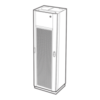
Product Specification for Power and Battery Cabinet
6.7 Product Requirements
6.7.1 Functional Requirements
MMI Handling
The PBC MMI functions provides the following:
• Supervision of the Antenna alarm signals
• Communication link between the AAU and the PBC
• Supervision of the PBC alarm signals
• Alarm signalling to the RBS
• User interface for installation settings and alarm presentation
Codes on display
Display 1 (D1) shows the unit number as follows:
0 = PBC
1 = Antenna part 1
2 = Antenna part 2
3 = Antenna part 3
4=
5 = Feeder A
6 = Feeder B
7 = Installation faults
Antenna part 2 and 3 are used if the antenna consists of more than
one unit.
Display 2 (D2) shows the severity of an alarm as follows:
0 = Not Classified
1 = Severe
2= Warning
The messages for the feeder values also use this element, see below.
Display 3 (D3) shows which type of error has occured or the command that
is transmitted to the AAU as follows:
0 = AC fault
1 = AC/DC fault
2 = DC/DC overload
3 = DC/DC fault
4 = Battery fault
EN/LZT 123 2697 R5A
1998-08-13
79 (306)
© Ericsson Radio Systems AB
— All Rights Reserved —
 Loading...