iPlex Installation and Hardware Specification Guide
17
a serial interface console port for local system access to the command line inter-
face (CLI), and an alarm port.
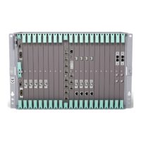
Front View
Rear View
The iPlex is NEBS Level 3 certified. It provides room for 8 submodule slots.
The close-up rear view image below shows a full chassis with eight submodules, a
console port, an alarm port, a control port, a redundancy port, and two GE ports.
Close-up Rear View
Switch Control
Module (SCM)
and Media
Control Module
(MCM)
iPlex is capable of supporting up to 2 Gbps of bandwidth through the backplane
and routing or switching data traffic at wire speed.
The Media Control Module is a portion of the iPlex system board that provides
submodule connectivity via the carrier card. The carrier card provides a standards-
based mezzanine interface for up to four submodule cards per carrier card, and up
to two carrier cards per chassis (thus up to eight submodule cards per iPlex).
ST
A
T
U
S
AC
TIVE
LI
NK
AC
TIVE
A
L
AR
M
POWE
R
O
N
LI
N
E
S
C
M
M
C
M
ET
H1
ET
H2
GE
1
GE
2
M
AJ
O
R
M
I
N
O
R
4
3
2
1
CONTROL
R
EDU
N
DA
NC
Y
CONS
OL
E
A
L
A
RM
GE1
GE
2
1
00
/
2
40 V
A
C
~
6
A
A
U
D
I
O
MPEG-2 ENC
CI/Y/SDI
C2/C
RDY ACT
A
U
D
I
O
MPEG-2 ENC
CI/Y/SDI
C2/C
RDY ACT
A
U
D
I
O
MPEG-2 ENC
CI/Y/SDI
C2/C
RDY ACT
MPEG-2 ENC
CI/Y/SDI
RDY ACT
A
U
D
I
O
C2/C
4321
4321
CONTROL
REDUNDANCY
CONSOLE
ALARM
GE1
GE2
100/240 VAC
~
6A
LINK
STATUS
IN
OUT
ATM/DS3
LINK
ATM/E3
STATUS
IN
OUT
S
T
A
T
U
S
MM
L
I
N
K
OC-3/STM-1
AT M
S
T
A
T
U
S
SM
L
I
N
K
OC-3/STM-1
AT M
RDY
ACT
RDY
ACT
ASI OUT
1A
1B
2A
2B
A
U
D
I
O
AVCenc
CI/Y/SDI
C2/C
RDY ACT
A
U
D
I
O
AVCenc
CI/Y/SDI
C2/C
RDY ACT
RDY
ACT
RDY
ACT
ASI IN
1A
1B
2A
2B

 Loading...


