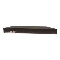
iPlex Installation and Hardware Specification Guide
37
Alarm Pinouts The following table provides the pin assignments for the Alarm Port Connector.
The following scheme shows the cable fitting for the alarm port.
Pin No. Connection
1
TANDBERG Television debug use – leave open
2
3 Critical Alarm output—normally open
4 Critical Alarm output—common
5 Status input 1—anode
6 Status input 1—cathode
7
TANDBERG Television debug use – leave open
8
9
10
11
12
13
14
15
 Loading...