S0740 800 152/E061012/P36
-- 5 --
ci01d1
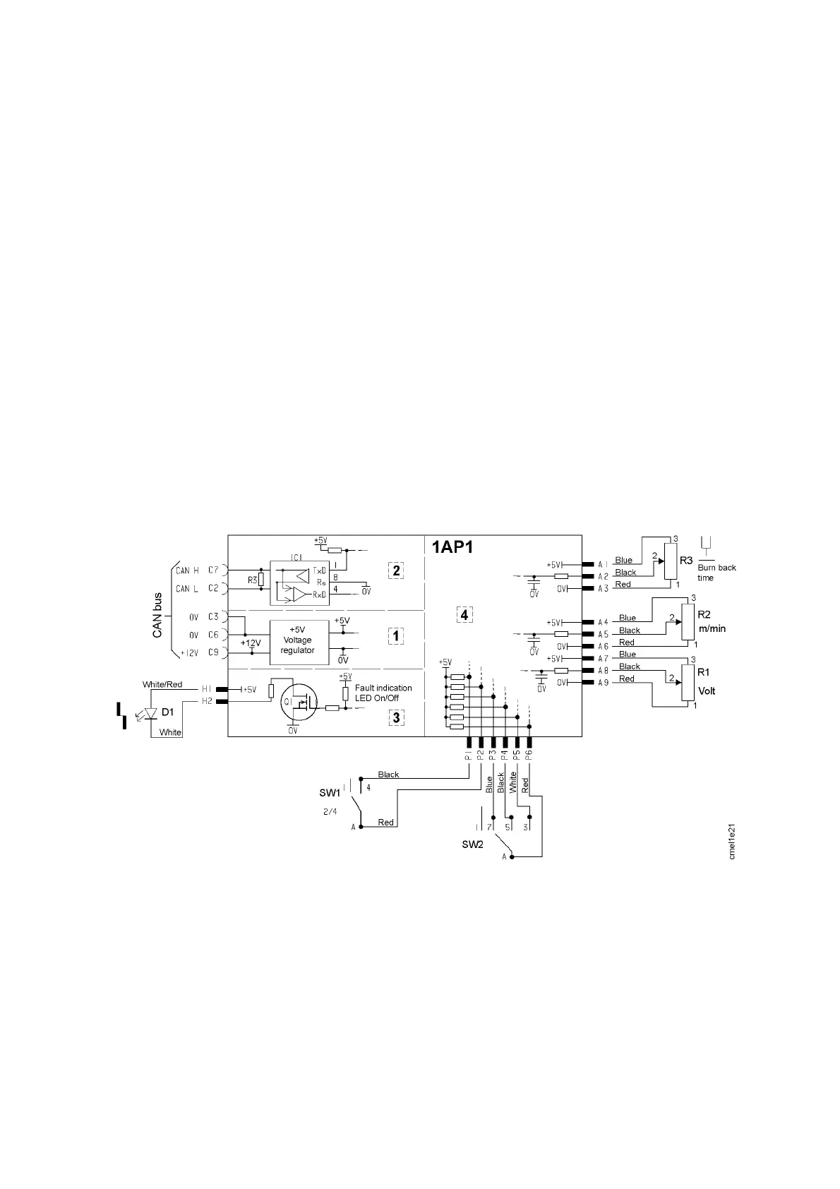
1AP1:2 Commu n ication
Communication between the control panel and the machine is via the system’s
CAN bus.
Resistor R3 is the terminating resistor (120 Ù) for the bus. Read more about
the CAN bus in the service manual for the power source.
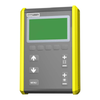
1AP1:3 Fault indication, panel M2
The M2 panel has a single fault-- indicating LED, which is controlled by
transistor Q1. The faults indicated by the LED are described on page 8.
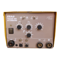
1AP1:4 Settings, panel M2
Welding settings from the M2 panel are made by rotary potentiometers and
switches:
R1: welding voltage SW1: 2--stroke or 4-- stroke control
R2: wire feed speed SW2: inductance
R3: burnback time
Wiring diagram for the M2 panel.
 Loading...