S0740 800 152/E061012/P36
-- 6 --
ci01d1
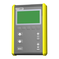
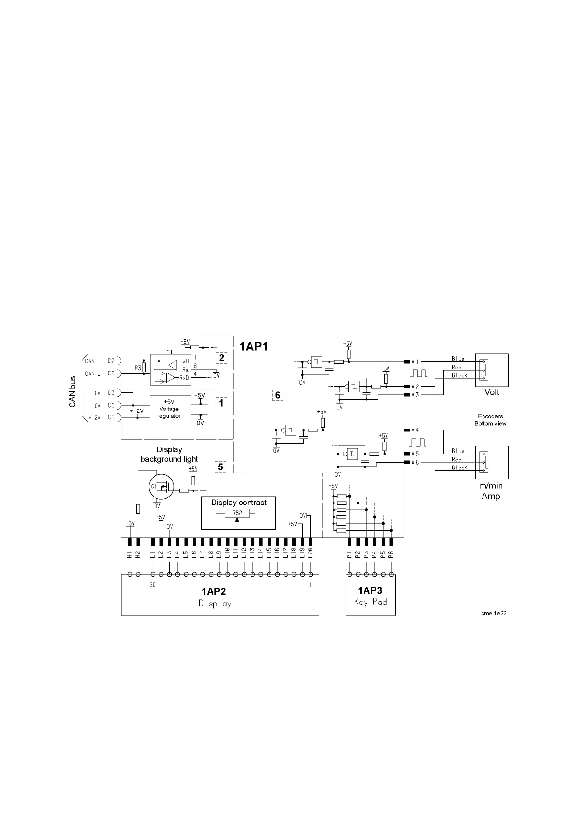
1AP1:5 Display, panels MA4, MA6 and U6
The MA4, MA6 and U6 display panels are backlit by parallel --connected LEDs,
controlled by transistor Q1. Display contrast can be adjusted b y potentiometer
R52: see the component positions diagram on page 7.
1AP1:6 Settings, panels MA4, MA6 an d U6
The MA4, MA6 and U6 panels have pulse generators (encoders) for setting
the welding voltage and wire feed speed, with pushbuttons for other functions.
Turnin g the voltage adjustment pulse generator briefly connects contact A3 (0
V) to contacts A1 and A2, but with a slight time difference between them. This
generates pulses that are displaced by about 90° relative to each other. The
processor senses which contact was first connected to 0 V, and decides
whether the voltage is to be increased or decreased.
When the pulse generator knob is not being turned, the voltage on contacts A1
and A2 is +5 V. The wire feed speed pulse generator operates in a similar
manner.
Wiring diagram for the MA4, MA6 and U6 panels.
 Loading...