24
3.3 ELECTRICAL INPUT CONNECTIONS
In order to provide a safe and convenient means to complete-
ly remove all electrical power from the machine, it is highly
recommended that a line disconnect switch be installed in
the input circuit of the machine.
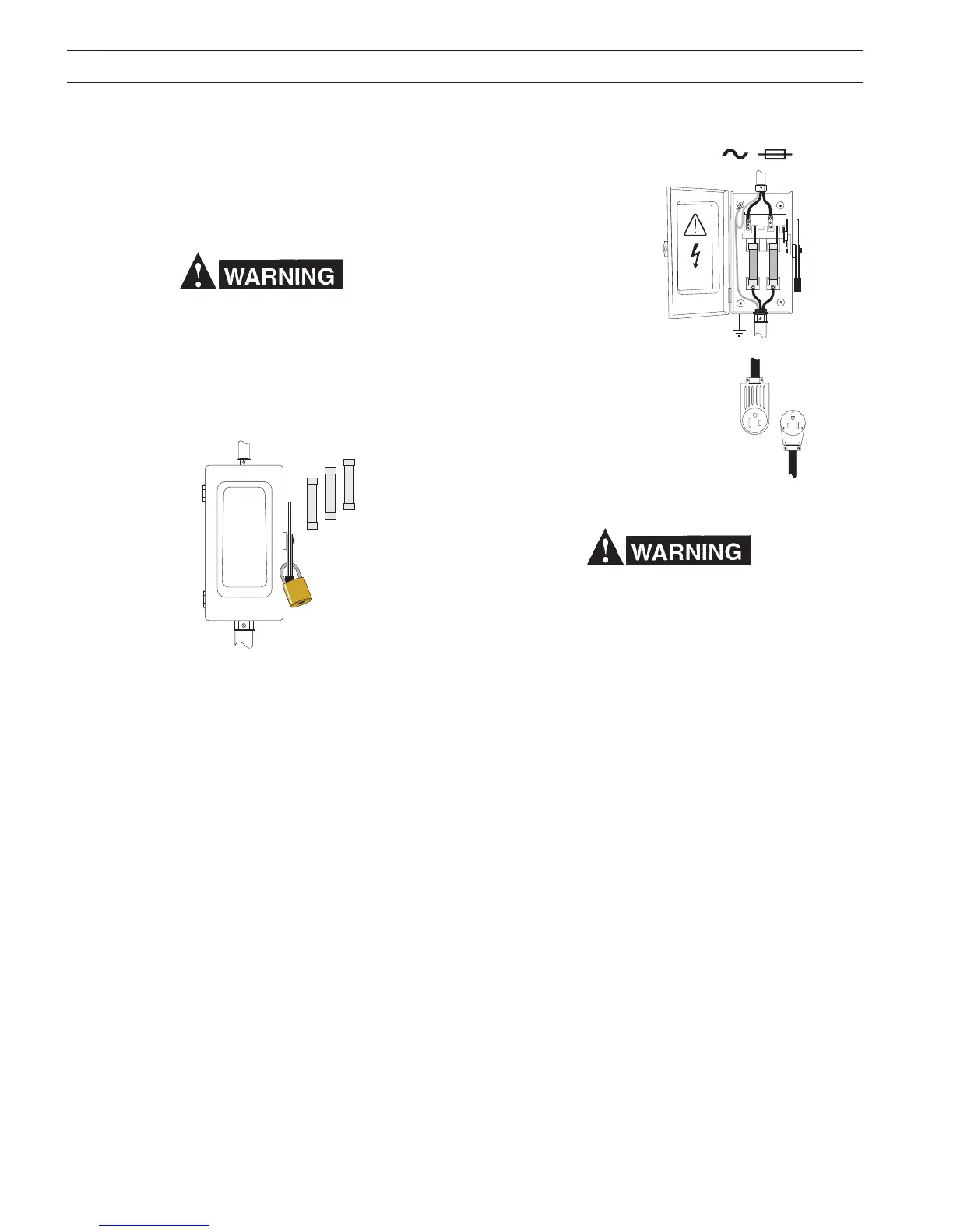
Before making electrical input connections to the weld-
ing machine, unplug the unit or use “Machinery Lockout
Procedures”. If the connections are to be made from a line
disconnect switch, the switch should be padlocked in the
o position. If the connection is to be made from a fuse-
box, remove the fuses and padlock the cover closed.
3.3.1 INPUT ELECTRICAL REQUIREMENTS
The primary input voltage requirements are shown on the
power source nameplate. The power source is designed
to be operated from 208/230 vac single phase 50/60 Hz or
230/460/575 vac single phase 50/60 Hz.
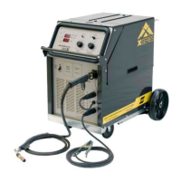
3.3.2 INPUT PLUG
The input power cord is provided with an attachment plug.
The plug will mate with a 250 volt, 50 Amp receptacle conform-
ing to NEMA 6-50R congura tion (208/230 vac model only).
The receptacle should be wired to a separately fused discon-
nect or circuit breaker by an electrician. This disconnect
or breaker can be wired to a single phase system or two
conductors of a three phase system. A third conductor for
grounding must be connected between the disconnect and
the receptacle.
The termi nal labeled GRD is connected to the power source
chassis and is for ground purposes only. This must be
connected to a good electrical ground. Do not connect
a conductor from the terminal labeled GRD to any one of
the L1, L2 terminals as this will result in an electrically hot
machine chassis.
3.4 VOLTAGE CHANGEOVER (Figure 4)
The voltage changeover terminal board is located in the tool
compartment on the left side of the machine. As shipped from
the factory, the Multimaster 300/300X is congured for the
highest connectable voltage. If using the other input voltages,
the links on the terminal board (TB) inside the unit must be
repositioned for the appropriate input voltage. See gures
4A - 4E for 60Hz input voltage congurations. To gain access
to the terminal board, open the access panel on the left side.
To change voltages, perform the following:
A. Remove the left screw ONLY and swing plexiglass door
upward.
B. Adjust the copper bar links to the primary voltage being
used.
C. Swing clear panel down and secure with screw.
Typical Installation -
User Supplied Power
Disconnect Box,
Receptacle and Plug
SECTION 3 INSTALLATION