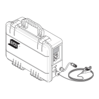
The ESAB RobustFeed AVS (Arc Voltage Sensing) is a portable wire feeder designed for welding applications. It is powered entirely by the arc voltage from either a constant current (CC) or constant voltage (CV) welding power source and operates with reversed polarity (Direct Current Electrode Positive - DCEP) or straight polarity (Direct Current Electrode Negative - DCEN).
Function Description:
The RobustFeed AVS unit is equipped with a four-wheel drive wire feed mechanism and control electronics, all housed within a sealed enclosure. It can be used with wire on ESAB's Marathon Pac™ or standard wire bobbins (Ø 200 mm and Ø 300 mm). The unit offers flexibility in placement, capable of being used on a trolley, suspended above the workplace, or directly on the floor (either standing up or lying down, with or without an optional wheel set).
The wire feeder's operation is controlled via both an external and an internal control panel. The external panel features a display and a knob for setting the wire feed speed. The internal panel includes a CC/CV switch, circuit breaker, main fuse, power switch, 2-stroke or 4-stroke selection switch, gas purging/wire inching switch, and a knob for setting the gas flow rate (optional).
In Constant Voltage (CV) mode, the wire feed speed knob controls the welding current, with clockwise rotation increasing the current and counter-clockwise rotation decreasing it. In Constant Current (CC) mode, the knob controls the arc voltage, with clockwise rotation increasing the arc voltage and counter-clockwise rotation decreasing it. The actual wire feed speed varies with arc voltage in CC mode. The display shows the preset wire feed speed in CV mode, and both wire feed speed and voltage in CC mode.
Usage Features:
- Lighting: The unit includes internal lights that automatically turn on when welding starts, when the left side door is opened, when the feeder is started, when parameters are changed on the internal control panel, or when wire inching is performed. These lights automatically turn off after a few minutes of inactivity.
- Bobbin Brake: The bobbin brake force is adjustable via a 0.236 in. (6 mm) hexagon Allen screw. It should be set just enough to prevent wire feed overrun, with the required force depending on wire feed speed and spool size/weight. Overloading the brake can affect welding quality.
- Wire Loading: The process involves opening the left door, removing the old spool, inserting a new one, straightening the wire, filing burrs, locking the spool, and threading the wire through the feeder mechanism.
- Feed Roller Changes: Feed rollers should be matched to the wire type. This involves unlocking the roller quick locks, relieving pressure on the rollers by folding down tensioner units, removing old rollers, installing new ones, reapplying pressure, and locking the rollers.
- Wire Guide Changes: Inlet, middle, and outlet wire guides may need to be changed to match the wire type. This involves unlocking quick locks, removing old guides, inserting new ones, and locking them into place.
- Roller Pressure Adjustment: Roller pressure is adjusted separately for each tensioner unit based on wire material and diameter. It's crucial not to set the pressure too high. A test involves feeding wire against an insulated object: at 0.197 in. (5 mm) from the object, rollers should slip; at 0.969 in. (50 mm), the wire should feed and bend. Approximate settings are provided in a weld data table.
- Control Panel Rotation: For horizontal use, the external control panel can be rotated 90° counter-clockwise by removing two screws, rotating the panel, attaching it in the correct position, and refastening the screws.
- Gas Purging: Used to measure gas flow or flush air/moisture from hoses before welding. It operates without voltage or wire feed.
- Wire Inching: Allows feeding wire without applying welding voltage.
- 2-stroke/4-stroke Selection: In 2-stroke mode, gas pre-flow starts with a trigger press, welding begins, and releasing the trigger stops welding and starts gas post-flow. In 4-stroke mode, the arc continues after the trigger is released (if established) until the trigger is pressed and released again, or the arc is broken manually.
- Shutdown: Release the torch trigger, turn off and disconnect all power, and turn off the shielding gas supply.
Important Technical Specifications:
- Power Supply Voltage: 15-100 VDC
- Maximum Weld Voltage: 45 VDC
- Power Requirement: 194 VA
- Rated Supply Current: 4.3 A
- Wire Feed Speed: 32-984 in./min (0.8–25.0 m/min)
- Torch Connection: EURO, Tweco 4
- Max. Diameter Wire Bobbin: 12 in. (300 mm)
- Wire Dimensions:
- Fe: 0.6 - 2 mm (0.023 - 0.078 in.)
- SS wire: 0.6 - 1.6 mm (0.023 - 0.062 in.)
- Cored wire: 0.9 - 2.4 mm (0.035 - 0.093 in.)
- Weight:
- RobustFeed AVS CSA, W/O flowmeter with Tweco connector: 40.1 lb (18.2 kg)
- RobustFeed AVS CSA, with flowmeter with Tweco connector: 40.5 lb (18.4 kg)
- Maximum weight wire spool: 44.1 lb. (20.0 kg)
- Dimensions (lxwxh): 23.4×9.8×16.9 in. (595×250×430 mm)
- Operating Temperature: -4 to +131 °F (-20 to +55 °C)
- Transport and Storage Temperature: -40 to +176 °F (-40 to +80 °C)
- Shielding Gas: All types intended for MIG/MAG welding
- Maximum Gas Pressure: 5 bar (0.5 MPa)
- Permissible Load at +40°C:
- 40% duty cycle: 500 A / 39 V
- 60% duty cycle: 450 A / 36 V
- 100% duty cycle: 350 A / 31.5 V
- Enclosure Class: IP44
- Lifting Capacity: Maximum total weight of 90 lb / 40 kg when lifted in the two outer upper lifting handles.
Maintenance Features:
- Regular Inspection: Important for safe and reliable operation.
- Wire Feed Mechanism:
- Regularly check for dirt and clean as needed.
- Clean and replace worn parts (pressure roller, feed roller, wire guide) at regular intervals. Excessive pretensioning can cause abnormal wear.
- Clean liners and other mechanical parts with compressed air if wire feed seems slow.
- Check and change nozzles, driving wheel, and cog-wheel package as needed.
- Bobbin Holder:
- Inspect the brake hub sleeve and nut for wear and proper locking at regular intervals. Replace if necessary.
- Welding Torch:
- Clean and replace wear parts (e.g., wire guide, contact tip) at regular intervals for trouble-free wire feed. Blow the wire guide clean regularly.
- Coolant: If equipped with an ESAB cooler, only ESAB-approved coolant should be used to avoid damage and maintain product safety.
- Troubleshooting: A table of fault symptoms and corrective actions is provided to assist before contacting an authorized service technician.
- Spare Parts: Only ESAB original spare and wear parts should be used. Ordering requires product type, serial number, designation, and spare part number.
Safety Precautions:
The manual emphasizes various safety precautions, including:
- Personal Protection: Wear welding helmet, safety glasses, face shield, flameproof gloves, heavy long-sleeve shirt, cuffless pants, high-topped shoes, and a welding helmet or cap. Protect bystanders with non-flammable partitions.
- Fire and Explosions: Keep combustibles away from the work area, clean workpieces of flammable substances, have fire extinguishing equipment ready, and inspect the work area after welding.
- Electrical Shock: Ensure power source and workpiece are properly earthed, use well-maintained equipment, keep everything dry, insulate yourself from the workpiece and ground, wear dry gloves, and turn off power before removing gloves.
- Electric and Magnetic Fields (EMF): Route electrode and work cables together, avoid coiling cables around the body, connect work cable close to the workpiece, and keep the power source and cables as far away as possible from the body. Welders with pacemakers should consult their doctor.
- Fumes and Gases: Work in well-ventilated areas, avoid breathing fumes, and do not weld on materials that produce toxic vapors.
- Cylinder Handling: Secure cylinders upright, use proper regulators, maintain hoses, and keep valves closed when not in use.
- Moving Parts: Keep all covers closed, stop engines before installation, and keep hands, hair, loose clothing, and tools away from moving parts.
- Falling Equipment: Use only the lifting eye, use adequate capacity equipment, and ensure lift forks extend beyond the opposite side of the unit.
- Maintenance: Only qualified personnel should perform installation, troubleshooting, and maintenance. Disconnect power before internal work. Maintain cables and safety devices. Use equipment only for its intended purpose and do not modify it.
- California Proposition 65 Warning: Notes that welding/cutting produces chemicals known to cause birth defects or cancer, and the product may expose users to lead.