5. Errors in the accuracy of the robot. Controller does not read the encoder, or fails to show
changes in encoder readings.
Qualified Technician Only:
•
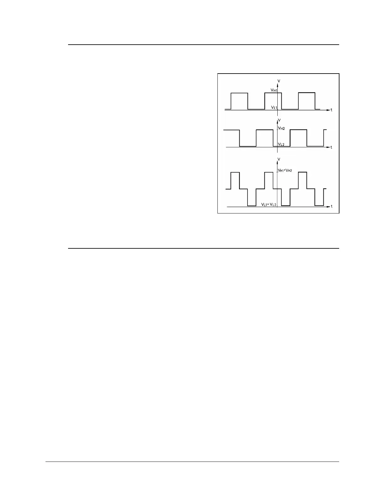
Using an oscilloscope, check the signals (P
0
and P
1
) received from the encoder’s two
phototransistors. Figure 15 shows the wave
diagrams which emanate from the two
channels of the encoder (P
0
and P
1
) with
respect to the time axis. The top two signals
should be clean square waves:
8
.
"*NQY+"XCNWG "UJQWNF"DG"2068"QT"NGUU0
8
*
"*JKIJ+"XCNWG"UJQWNF"GZEGGF"6"80
In addition, check the third wave, which
shows the sum of the two waves. The
diagram reflects a time shift of a quarter
cycle between the two waves.
If the waves are distorted with an incorrect
shift between them, the encoder is faulty and
should be adjusted or replaced.
6. Errors in the repeatability of the robot.
Qualified Technician Only:
•
Try to identify the faulty axis. If many or all axes are faulty, look for an electrical
noise source in your environment.
•
Check the encoder. Follow the procedures in Item 3 and Item 4.
•
If no problem found by means of Items 8 and 9, do the following:
•
Bring the robot to a starting position. Using a pencil, draw a fine, continuous line
on the robot which crosses from one link to the adjacent link at the joint in question.
5GNGEV"8KGY^'PEQFGTU"VQ"FKURNC["VJG"GPEQFGT"TGCFKPIU0
'PVGT"VJG"EQOOCPF"%QPVTQN"1HH"*VQ"FKUCDNG"UGTXQ"EQPVTQN+0
2J[UKECNN["OQXG"VJG"CZKU"VQ"CPQVJGT"RQUKVKQP0"6JGP"TGVWTP"VQ"VJG"UVCTVKPI
RQUKVKQP"OCTMGF"D["VJG"NKPG"[QW"FTGY0"%JGEM"VJG"GPEQFGT"TGCFKPI"HQT"VJG"CZK U
CICKP0"+V"UJQWNF"DG"YKVJKP"UGXGTCN"EQWPVU"QH"VJG"HKTUV"TGCFKPI0"4GRGCV"VJKU"UVGR
C"PWODGT"QH"VKOGU0"+H"VJG"GTTQT"KP"VJG"GPEQFGT"TGCFKPI"CEEWOWNCVGU."VJG
GPEQFGT"PGGFU"VQ"DG"TGRNCEGF0
•
Check the transmission for loose points or damage. Check for continuity of
movement in all the relevant transmission components (gears and belts moving
together with the drive shaft of the motor).
Figure 15: Encoder Signals
User’s Manual 19 SCORBOT-ER 4pc
9810
 Loading...