IVX 20 Hardware overview/installation
B.7
Expansion card installation
Adding or replacing the expansion card will require the system to be taken out of service. Wear a
grounding strap and avoid unnecessary movement while handling the circuit boards.
1.
Unplug the power supply to IVX.
2.
Remove the cabinet lid as described earlier.
3.
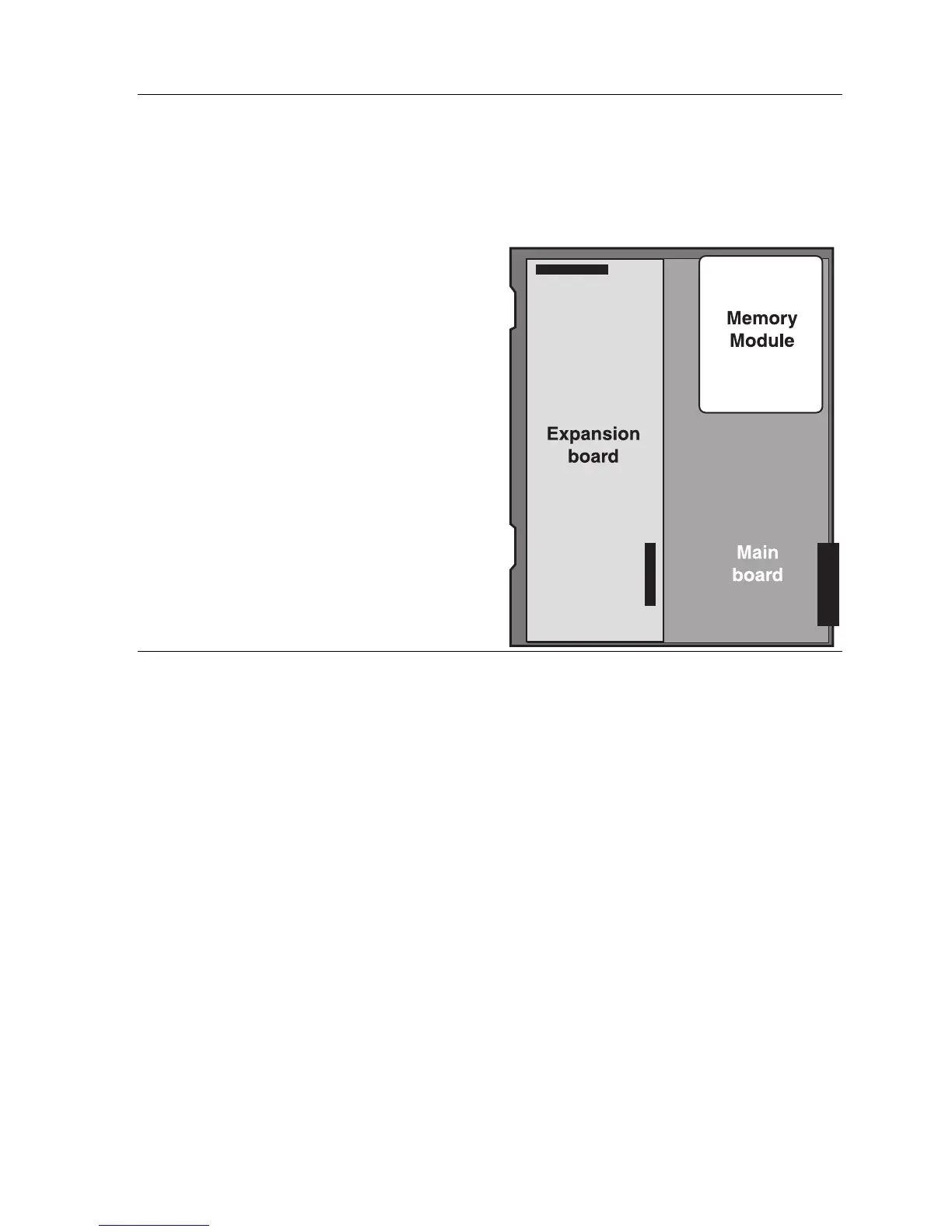
The expansion card snaps directly onto two
50-pin connectors located on the upper-left
side and bottom center of the main board.
Note the orientation of the connectors and
those on the expansion card.
4.
The expansion card is installed with the
component side up (the pins from the main
board will pass through the back of the
board). Line up the card with the connectors
and snap into place, being careful not to
apply excessive pressure.
5.
Install the retaining screws to the standoffs.
6.
Replace the lid.
7.
The external connections for the expansion
card are made through the original amphenol
connector on the main board. Simply punch
down the additional connections to the
appropriate pins on the 66 block. (See the 66
block wiring diagram, page B.15).
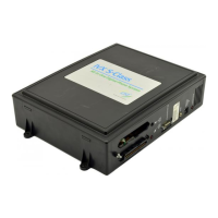
Memory Module
Note: The Memory Module is formatted with a proprietary format — do not attempt to install a non-
ESI drive.
Adding or replacing the Memory Module will require that the system be taken out of service.
If the Memory Module must be replaced, all configuration data and customer recordings will
be lost.
Contact the factory for a replacement Memory Module and detailed instructions for its installation.