64 Network Controllers Manual
REV_ ___ _________IC ___ ________
CHECK SUM_ _________________
COMPONENT SIDE
LAMP
TEST
P1
JP1JP2
+PWR- +CH1- +CH2-
TB1
[NWC-033.CDR]
LD1
LD2
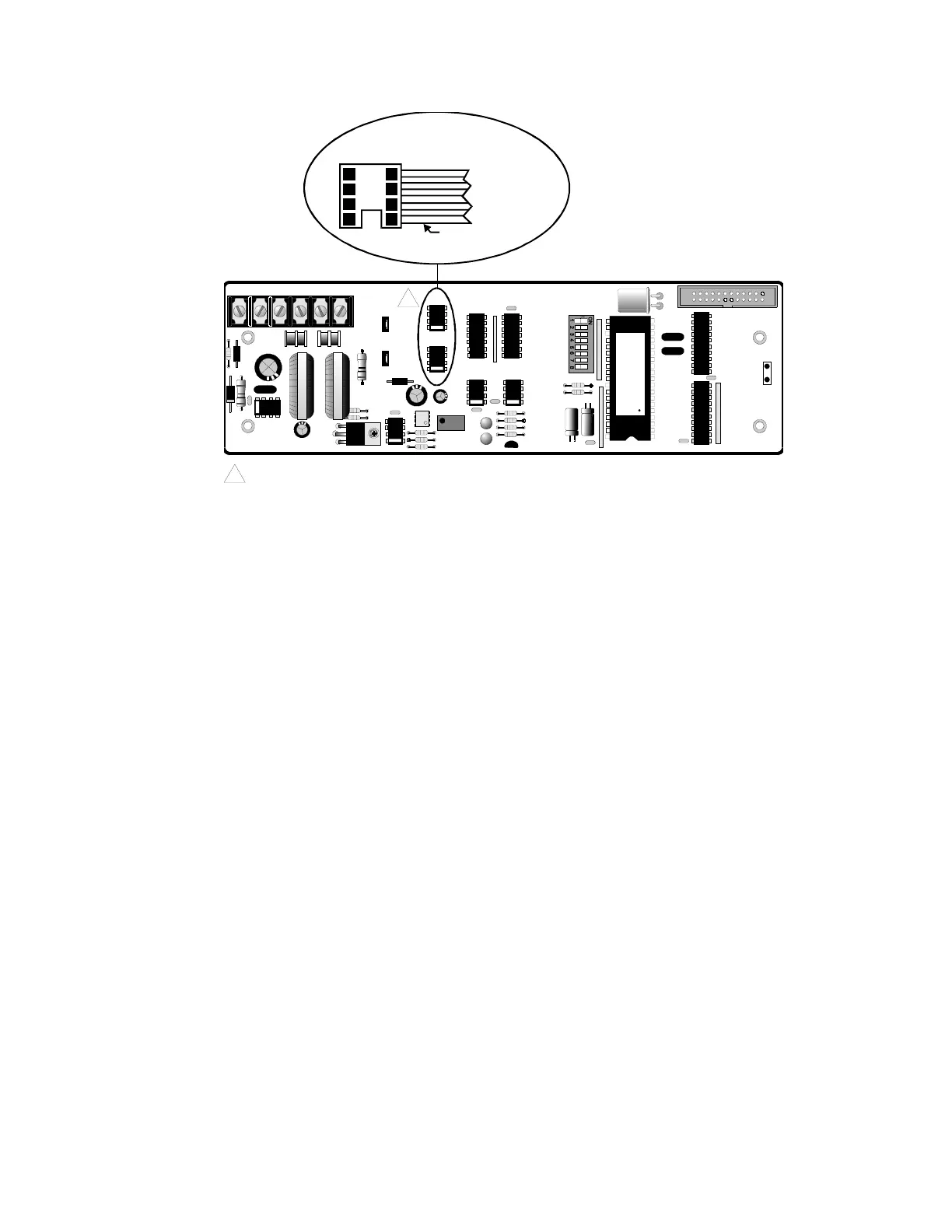
RED STRIPE
RIBBON CABLE TO
SO-FIB OR SO-20D
HEADER REPLACEMENT FOR
SERIAL FORMAT COMMUNICATIONS.
DETAIL A
1
1
FOR SERIAL FORMAT COMMUNICATIONS REPLACE
U3 FOR STYLE 4 AND U3 & U4 FOR STYLE 7
WITH HEADER/RIBBON CABLE ASSEMBLY.
RED STRIPED EDGE OF RIBBON CABLE MUST BE
INSTALLED TOWARDS NOTCHED (PINS 1 & 8) END
OF U3/U4 SOCKET. SEE DETAIL A.
N
NNE
TI
N
T
TB1-
T
TB1-
.
SAN-CPU to SO-FIB Connections
Jumper Setup
JP1 Install for constant output on FONC 4 for fiber testing ONLY.
JP2 Install for constant output on FONC 2 for fiber testing ONLY.
JP3* Install in “O” for old style FIB-20 Card, “N” for new style
FIB-20 card.
JP4* Install in “O” for old style FIB-20 Card, “N” for new style
FIB-20 card.
JP5 Future use option. Remove for normal operation.
*Use the “O” position unless specifically directed otherwise.
Indicators
LD-1 Red LED. Indicates module transmitter activity.
LD-2 Red LED ON. Indicates module active.