Network Controllers Manual 63
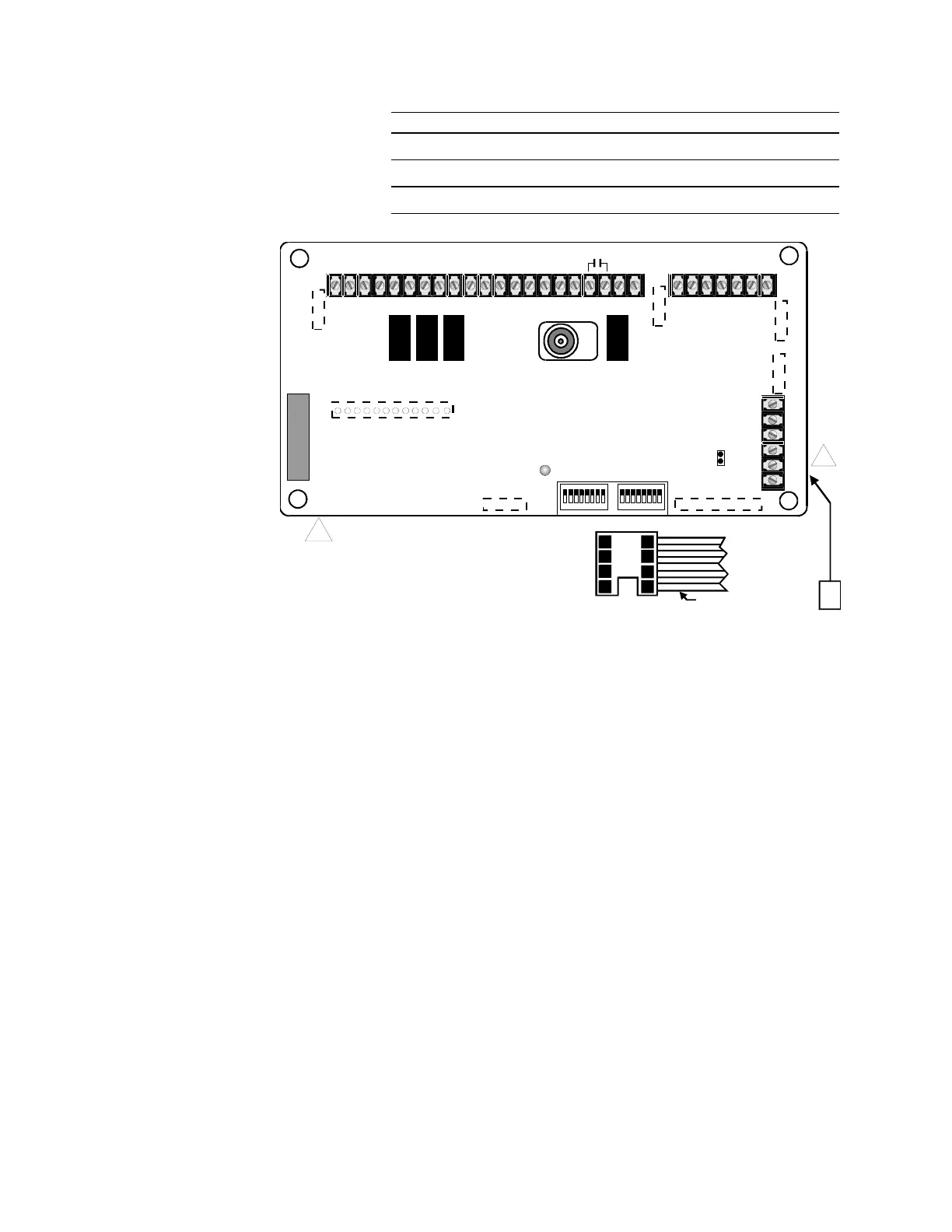
Board (P/N 150055)
MST (P/N 150033) U5 N/A
REM (P/N 150031) U10 U11
SAN CPU (P/N 150125) U3 U4
P3
P7
P6
P8
24V
5V
COM
DATA
EARTH
SHLD
+
24V
PWR
-
+
DATA
-
TB3
TB2
P5P2
P1
P4
CHANNEL 2 CHANNEL 1
DATA LINE
TERMINATION
JUMPER
112
AUX SUPV PREAMP OUT AUX IN
BUZZER
ACTIVITY
PREAMP
OUTPUTS
AUXILARY
INPUTS
AUXILARY
SUPV.
START
TELEPHONE
RISER
BUSY
RISER
EXTERNAL
TB1
1
1
2
2
3
3
4
4
5
5
6
6
7 8 9 101112131415 1617181920 21
CH2 CH1 CH2 CH1 CH1 CH2
CH1 SHLD CH2
8 7 6 5 4 3 2 1 8 7 6 5 4 3 2 1
DATA
ACTIVITY
LED
+ IN -
+ 1 - + 2 -
SHLD
+
-
1
1
FOR SERIAL FORMAT COMMUNICATIONS
REPLACE U2 ON LOWER PC BOARD
WITH HEADER/RIBBON CABLE ASSEMBLY.
RED STRIPED EDGE OF RIBBON CABLE MUST
BE INSTLLED TOWARDS NOTCHED (PINS 1 & 8)
END OF U2 IC SOCKET. SEE DETAIL A.
N
NNE
TI
N
T
TB
-4
TB
-
RED STRIPE
RIBBON CABLE TO
SO-FIB OR SO-20D
DETAIL A
[NWC-032.CDR]
U2
FCCA-4/6 to SO-FIB Connections