ES4440.2 Compact Failure Simulation Module - User’s Guide 17
ETAS Introduction
• Signal lists with all signals of a selected failure set. This is where the signal
is selected for which an failure is to be simulated.
• Display of all available failures for a selected signal in one window
• Failures are selected in this window by mouse click
• Settings of the desired failure duration
• Triggering the failure by mouse click
• Configuration of the Ethernet and CAN interface
• Configuration for master/slave operation
• Self-test and fuse test
• Automated control (with the LABCAR-PINCONTROL controller)
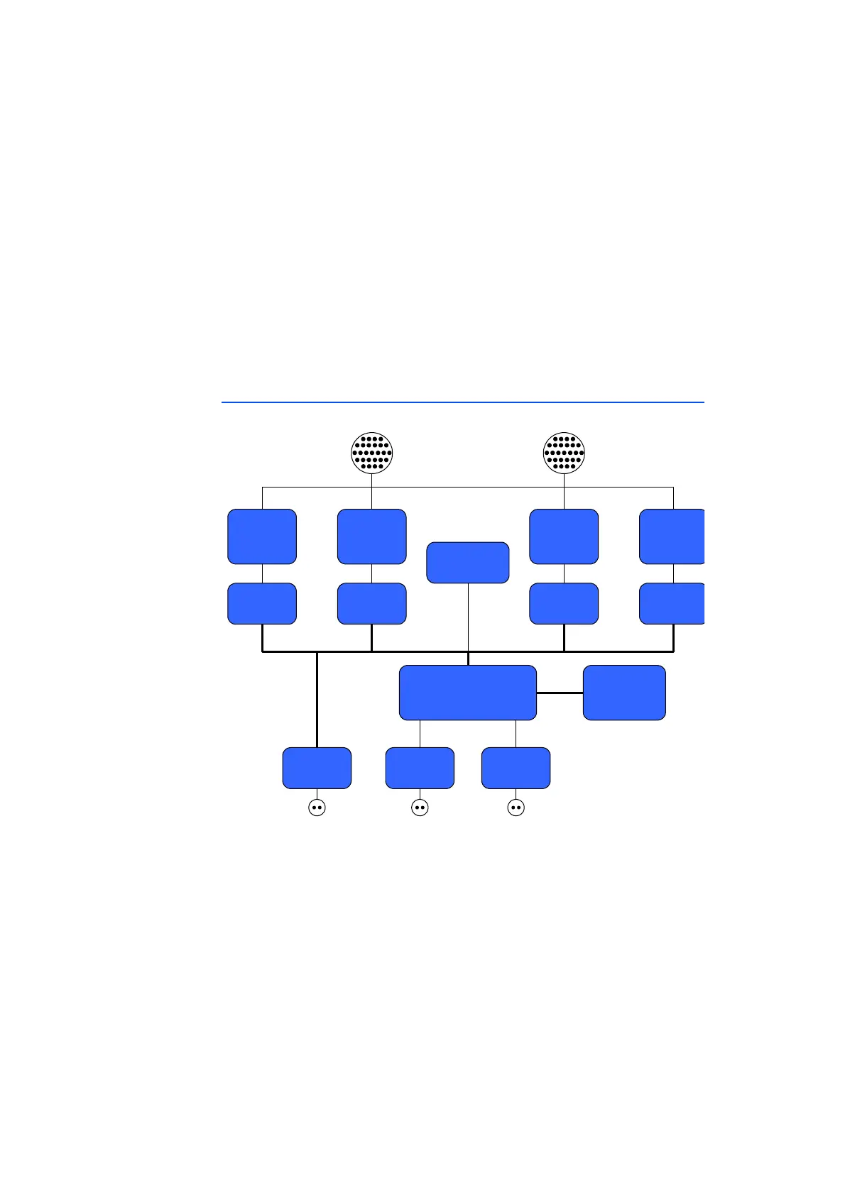
1.7.4 Block Diagram
Fig. 1-3 Block Diagram of the ES4440.2 Compact Failure Simulation Module
The core of the ES4440.2 Compact Failure Simulation Module is a micro-
controller (μC) with an integrated Ethernet controller – the μC is connected
directly to Ethernet-PHY. A CAN transceiver acts as a second interface to control
the ES4440.2.
A serial, non-volatile EEPROM saves a range of specific parameters such as MAC
address, IP address, CAN baud rate. Three PLDs with subsequent relay drivers
address the relays and MOSFETs.
A further feature is the fuse monitoring by the μC.
Relays for
Resistor
Cascade
20 A Relays
(64 Channels)
80 V Relays
(16 Channels)
MOSFET
EEPROM
Ethernet
PHY
µC
MOSFET
Driver
Relay DriverRelay Driver Relay Driver
Fuse Monitor
SYNC
CAN
Transceiver