ES4440.2 Compact Failure Simulation Module - User’s Guide32
Pin Assignment ETAS
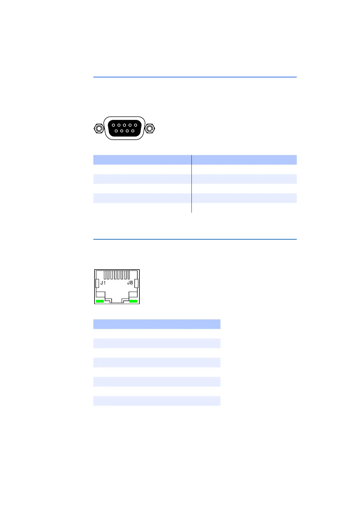
3.2 ”CAN” Connector
The signals for communication via the CANbus are pending at the ”CAN” con-
nector.
Type: DSub 9-pin (female)
Counterpart: DSub 9-pin (male)
Fig. 3-2 ”CAN” Pin Assignments (View from Front of Housing)
Tab. 3-2 ”CAN” Pin Assignment
3.3 ”Ethernet” Connector
The ”Ethernet” connector is used for the Ethernet connection to the host system
or an Ethernet switch.
Type: RJ45
Fig. 3-3 ”Ethernet” Pin Assignments (View from Front of Housing)
Tab. 3-3 ”Ethernet” Pin Assignment
Pin Assignment Pin Assignment
1n.c. 6GND
2 CAN Low 7 CAN High
3GND 8 n.c.
4 n.c. 9 n.c.
5 n.c. Housing PE
Pin Signal Meaning
1 TX+ send data, plus
2 TX-. send data, minus
3 RX+ receive data, plus
4 n.c. reserved
5 n.c. reserved
6 RX- receive data, minus
7 n.c. reserved
8 n.c. reserved