ES4440.2 Compact Failure Simulation Module - User’s Guide 23
ETAS Hardware Features
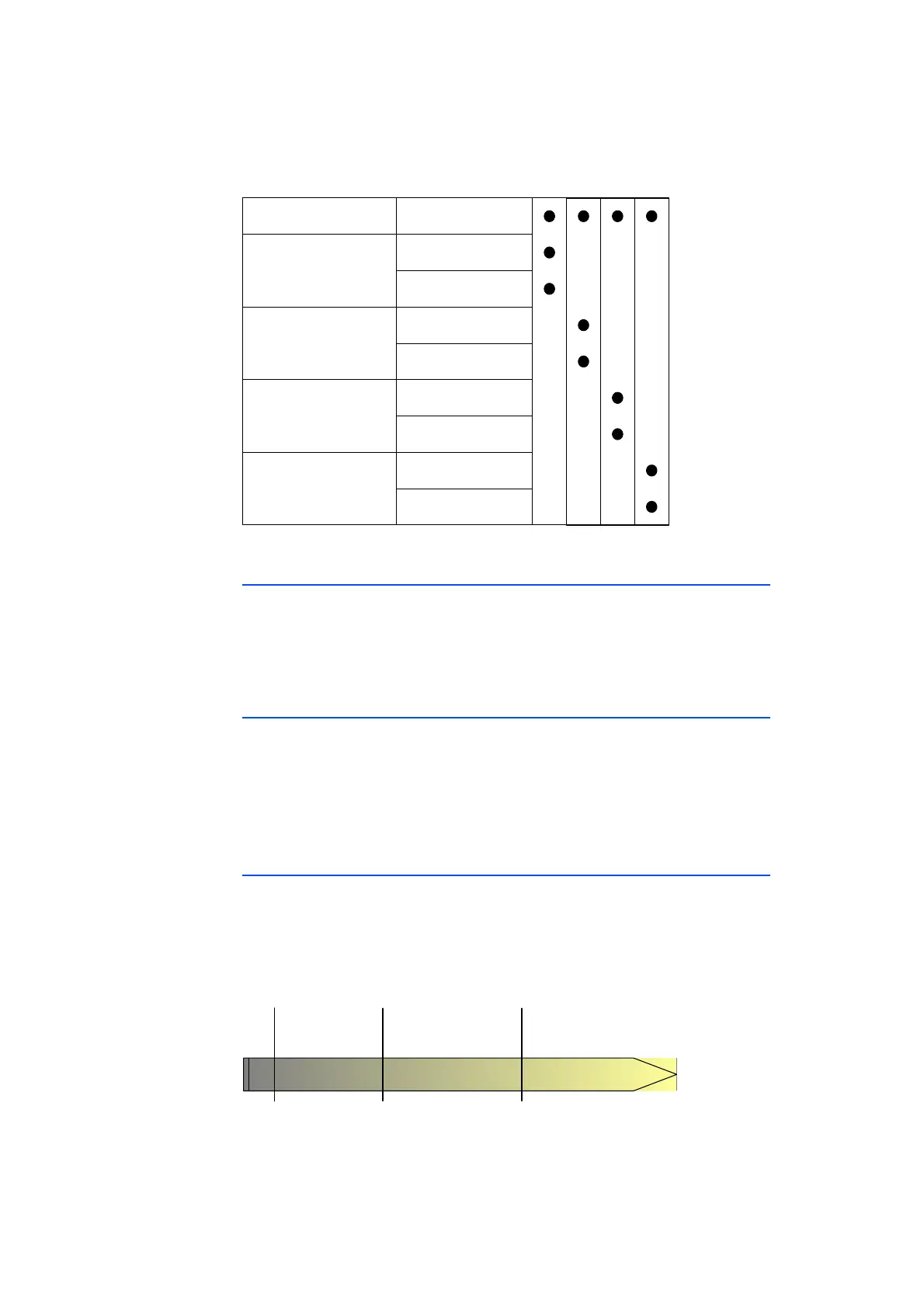
Failures which are switched by MOSFETS can only be activated individually.
Fig. 2-3 Failures Which Can Be Simulated Simultaneously
2.2.7 Decoupling the Load before Failure Activation
Normally the ES4440.2 is switched between the ECU and the LABCAR or
between the ECU and the real vehicle. The following takes place to ensure that
no channels of the LABCAR or components of the real vehicle are destroyed by
shorts: if an failure is switched without a load, the connection to the load is
interrupted before the failure is activated.
2.2.8 Measuring the Current
When failures are simulated in which both failure rails are used (line resistance,
short or resistance between two lines or leakage current), the current flowing via
the rails can be measured. For this purpose, a current measuring device is con-
nected to the ”Current” connector on the front panel and measuring is activated
with the command CurrentMeasurement()
(see ”LABCAR-PINCONTROL V–User's Guide”).
2.3 Time Response
If you are using mechanical relays and have to determine how long an failure has
to be active ((t
2
-t
1
) in the figure) until an entry is made in the failure memory,
the finite activation time of the mechanical relays has to be taken into consider-
ation.
In the following figure, this is the time (t
1
-t
0
), i.e. the time between the receipt
of the command and the actual closing of the relay.
Open Load
Short Circuit
to
+UBatt_A (Rail 1)
Short Circuit
to
+UBatt_B (Rail 2)
Load connected
Load disconnected
Short Circuit
to
-UBatt_A (Rail 1)
Short Circuit
to
-UBatt_B (Rail 2)
-
Load connected
Load disconnected
Load connected
Load disconnected
Load connected
Load disconnected
Time
Receipt of
command
t
0
t
1
t
2
Error is active
(relay closed)
Entry in
error memory