ES4440.2 Compact Failure Simulation Module - User’s Guide20
Hardware Features ETAS
2.2 Failure modes
In the following description of all available failures, the failures are shown sepa-
rately according to the type of channel (high-voltage or high-current channels).
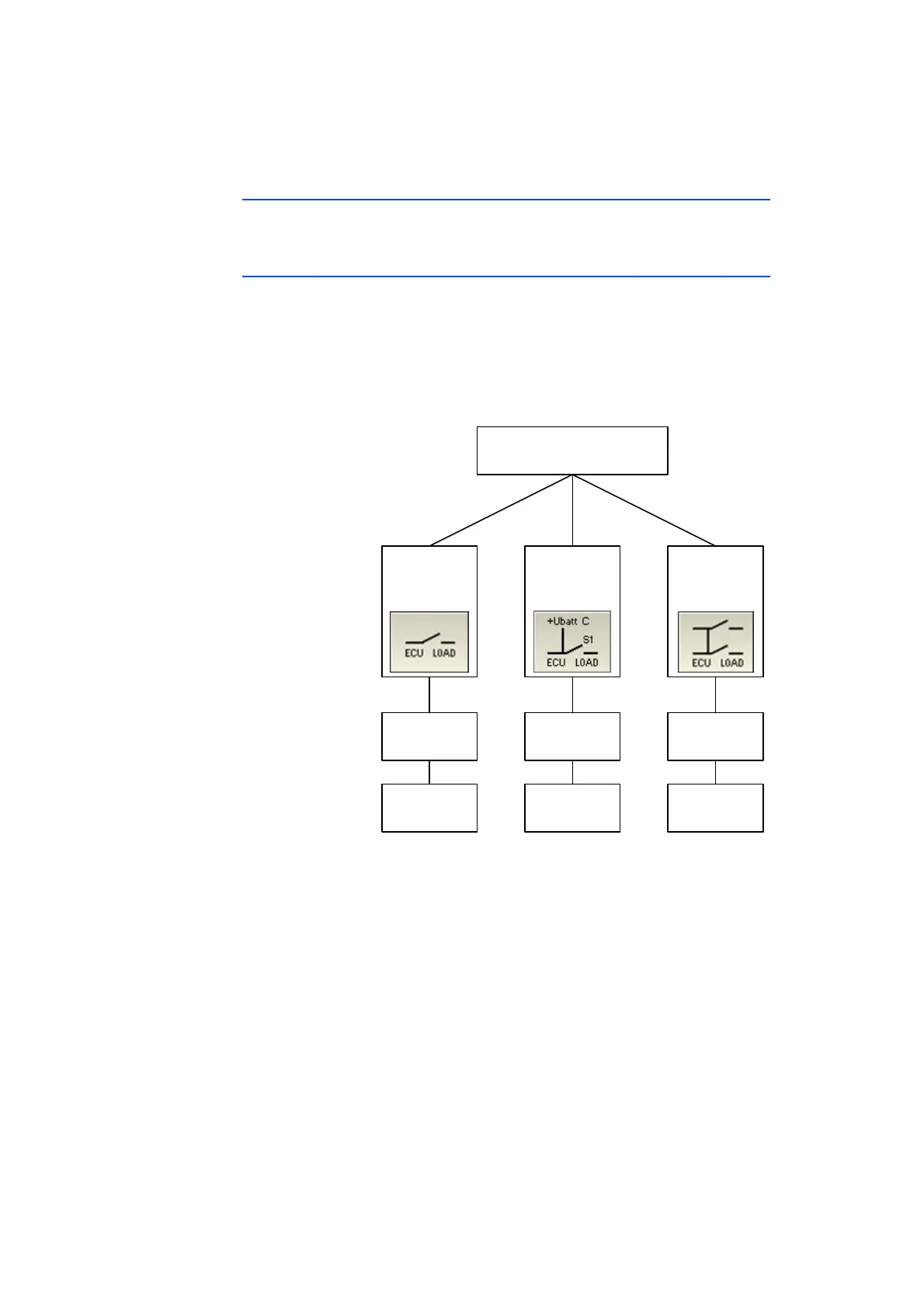
2.2.1 Failures for High-Voltage Channels
The following figure shows
• the failures which can be realized on the 16 high-voltage channels,
• whether several failures can be activated simultaneously,
• the settable duration of the failure state and
• whether this failure can also be realized in PWM control as a loose con-
tact.
Fig. 2-1 Failures for High-Voltage Channels
High-Voltage Channel
Error Type
Switched by
(Single/Multiple
Error)
Duration
(fixed or PWM)
Open Load
Relay
(single)
20 ms - 60 s
or
Short Circuit
to
±UBatt_C
Relay
(single)
Short Circuit
Relay
(single)
20 ms - 60 s
or
20 ms - 60 s
or