ES4440.2 Compact Failure Simulation Module - User’s Guide 35
ETAS Pin Assignment
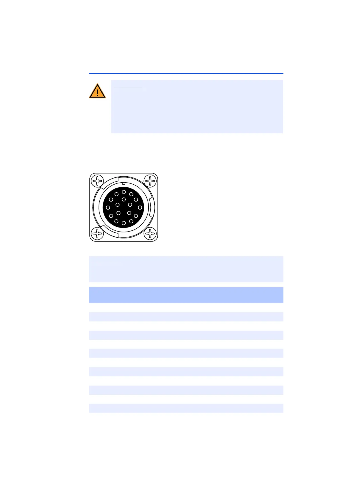
3.7 ”LOAD HV” Connector
The 16 high-voltage channels of the ECU are connected to the loads via these
two connectors.
Type: ITT Cannon CA02COM-E20-29S-B (female)
Counterpart: ITT Cannon CA06COM-E20-29P-B (male)
Fig. 3-6 ”LOAD HV” Pin Assignments
Risk of electric shock!
There could be extremely dangerous high voltages at the individual
pins of the "ECU HV" and "LOAD HV" connections. Therefore you
should only open the housing when the device has been discon-
nected from the mains power and all other connections have been
removed.
The lines of the signals ”LOAD0” and ”LOAD1” ... ”LOAD14” and ”LOAD15”
are all ”twisted pairs” within the ES4440.2!
Pin Signal Internally Connected to Connector
”ECU HV” - Pin:
ALOAD0ECU0
B LOAD1 ECU1
CLOAD2ECU2
D LOAD3 ECU3
ELOAD4ECU4
F LOAD5 ECU5
GLOAD6ECU6
H LOAD7 ECU7
JLOAD8ECU8
K LOAD9 ECU9
L LOAD10 ECU10
M LOAD11 ECU11
Tab. 3-6 ”LOAD HV” Pin Assignment