ES4440.2 Compact Failure Simulation Module - User’s Guide34
Pin Assignment ETAS
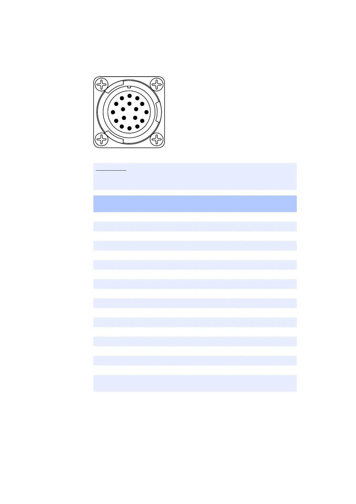
Counterpart: ITT Cannon CA06COM-E20-29S-B (female)
Fig. 3-5 ”ECU HV” Pin Assignments
The lines of the signals ”ECU0” and ”ECU1” ... ”ECU14” and ”ECU15” are all
”twisted pairs”!
Pin Signal Internally Connected to Connector
”LOAD HV” - Pin:
A ECU0 LOAD0
B ECU1 LOAD1
C ECU2 LOAD2
D ECU3 LOAD3
E ECU4 LOAD4
F ECU5 LOAD5
G ECU6 LOAD6
H ECU7 LOAD7
J ECU8 LOAD8
K ECU9 LOAD9
L ECU10 LOAD10
M ECU11 LOAD11
N ECU12 LOAD12
P ECU13 LOAD13
R ECU14 LOAD14
S ECU15 LOAD15
T**
* The pins T of „ECU HV“ and „LOAD HV“ are directly connected with each
other
Tab. 3-5 ”ECU HV” Pin Assignment