ES4440.2 Compact Failure Simulation Module - User’s Guide24
Hardware Features ETAS
Once the failure is set, measuring this activation time is executed on a reference
relay and transferred to the host in the command response.
For failures which are switched by MOSFETs, this kind of measuring is not neces-
sary due to fast activation.
2.4 Resistor Cascade
To simulate contact corrosion and crosstalk between ECU channels, the
ES4440.2 Compact Failure Simulation Module has a cascade of 14 resistors with
which resistances of 2 to approx. 32 k can be generated (in 2 intervals).
The individual resistors are activated (relay open) or bridged by 20 A relays. The
cascade consists of the following resistance values: 2, 4, 6, 16, 32, 64, 128, 256,
512, 1024, 2048, 4096, 8192 and 16384 .
The maximum permissible current depends on the voltage drop over the cascade
– it is 3 A with a voltage drop of 14 V and 1 A with a voltage drop of 30 V. As an
failure state is normally only ever active for a very short time, it is not a problem
if these values are exceeded briefly.
If, however, overheating does occur, temperature sensors cause an failure mes-
sage to be issued, the occurrence of which results in a system reset (see "Reset-
ting on Overtemperature" on page 27).
2.5 Status Displays via LEDs on the Front Panel
There are several LEDs on the front panel of the ES4440.2 Compact Failure Sim-
ulation Module, the meaning of which is described in this section.
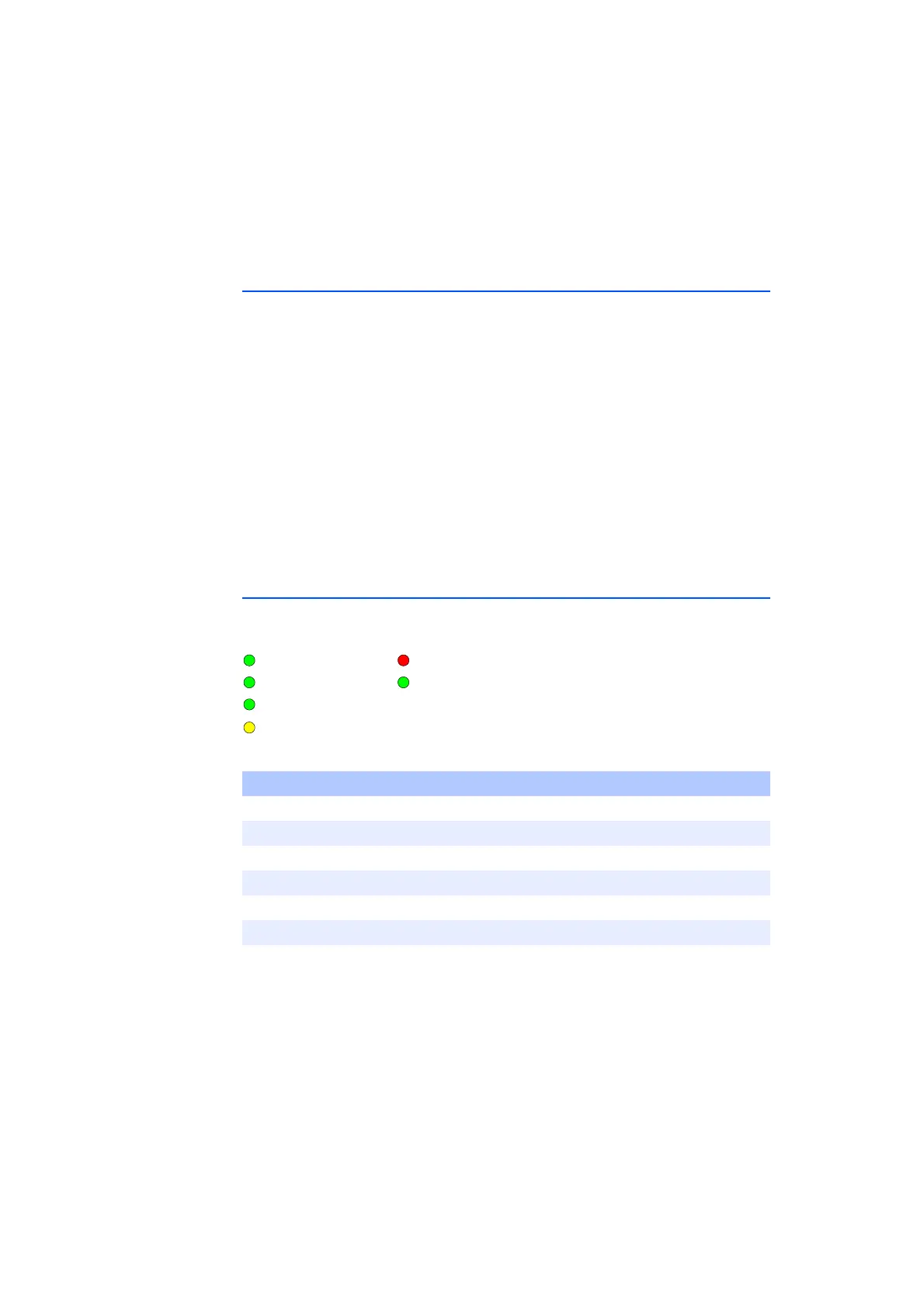
Fig. 2-4 LEDs on the Front Panel
Tab. 2-2 The Meaning of the LEDs on the Front Panel
Name Color Meaning
+24 V Green +24 V OK
+5 V Green +5 V OK
+3.3 V Green +3.3 V OK
Reset Yellow A reset takes place
System Failure Red ES4440 system failure
Failure Active Green An failure state is active
+24 V
+5 V
+3.3 V
Reset
System Error
Failure Active