ES4440.2 Compact Failure Simulation Module - User’s Guide 31
ETAS Pin Assignment
3 Pin Assignment
This chapter contains the description of the pin assignment of the connectors of
the ES4440.2 Compact Failure Simulation Module.
These are:
• "”SYNC” Connector" on page 31
• "”CAN” Connector" on page 32
• "”Ethernet” Connector" on page 32
• "”Current” Connector" on page 33
• "”Rail 1/2” Connector" on page 33
• "”ECU HV” Connector" on page 33
• "”LOAD HV” Connector" on page 35
• "”ECU CH0-CH42” / ”ECU CH43-CH63” Connector" on page 36
• "”LOAD CH0-CH42” / ”LOAD CH43-CH63” Connector" on page 40
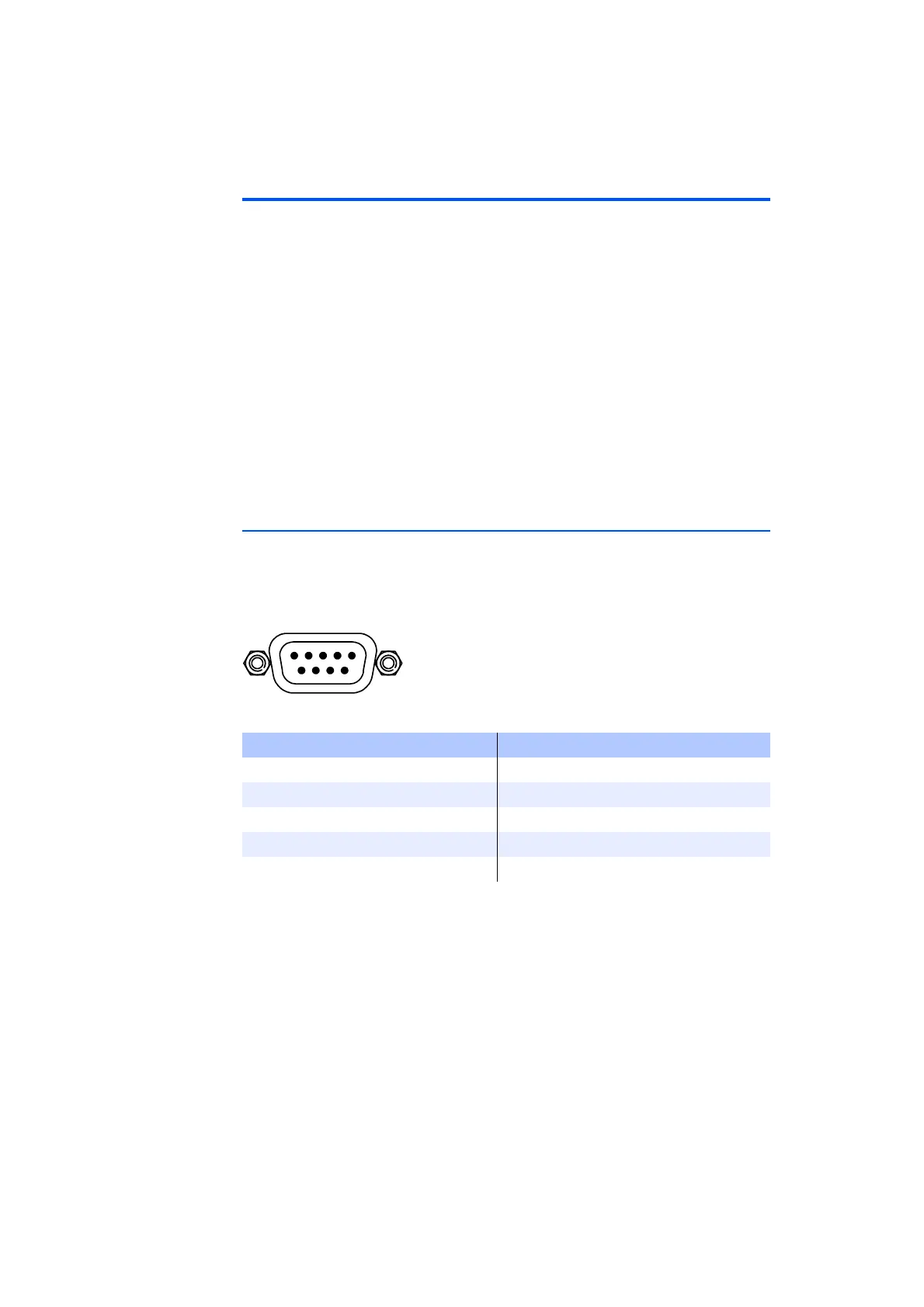
3.1 ”SYNC” Connector
The synchronization signals for the master/slave operation of several ES4440.2
Compact Failure Simulation Modules are pending at the ”SYNC” connector.
Type: DSub 9-pin (male)
Counterpart: DSub 9-pin (female)
Fig. 3-1 ”SYNC” Pin Assignments (View from Front of Housing)
Tab. 3-1 ”SYNC” Pin Assignment
Pin Assignment Pin Assignment
1 Reserved 6 n.c.
2 n.c. 7 n.c.
3n.c. 8Sync
4 n.c. 9 n.c.
5 GND Housing PE